The original Georgia Street Bridge, constructed in 1914, was a 30-ft-wide reinforced concrete, three-hinged, three-rib arch bridge.
The bridge was approximately 71.5 ft long and generally symmetrical about both the longitudinal and transverse axes. The deck was a continuous slab system with discontinuous “floating” slabs at the center and the two end spans. Arch-rib compression hinges were located at the apex and at the two rib footing connections of each arch. The combination of the three arch hinges and three floating slabs resulted in a structure that was vertically statically determinate with a well-defined load path. In contrast, the lateral load path was complex, discontinuous and unreliable.
The original abutments are 30-ft-wide and approximately 30-ft-tall anchor-block walls supported on narrow footings. The original abutment walls are 12 to 15 in. thick and span between four vertical beams placed 10 ft on center. The vertical beams extend between anchor blocks (deadmen) near the top of the walls and a shallow 2-ft-deep passive resisting embedment at the base of the walls. The original superstructure was connected to the abutments through the floating deck slabs, which were simply supported on the top of the abutment walls. The floating slabs were a compression-only connection and had unreliable transverse shear keys.
The total length of each of the four retaining walls is approximately 640 ft beyond the limits of the bridge. Each wall’s height varies from zero to slightly over 30 ft. Where the wall height exceeds 5 ft, anchor blocks installed near the top provide restraint.
The anchor blocks were placed near the top of buttresses that are spaced at 10-ft intervals. The original walls extended 2 ft below the sidewalk to develop a small passive resistance. There are no additional wall foundations.
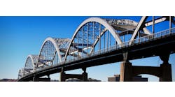
A streetcar passes underneath the original Georgia Street Bridge, which was constructed in 1914.
All that was wrong
Over the past 100 years, the bridge and walls have undergone a substantial number of repairs and modifications including extensive patching, multiple layers of shotcrete, filled barrier openings, removal of lighting, and the addition of a thick asphalt overlay to the roadways on and below the bridge. Degradation of the concrete and reinforcement is visually apparent throughout the structure, despite the placement of many layers of shotcrete.
The 2009 Bridge Inspection Report (BIR) identified many locations where spalling or incipient spalling, severe cracks and exposed bars had occurred. The AC overlay, almost 1 ft thick, was in poor condition, cracked and worn out. Several concrete spalls on the exterior arch rib, soffit, columns, barrier posts and caps also were documented.
Several previous studies had been conducted to assess repair, retrofit and replacement options for the bridge. Extensive material tests were performed. Core samples of the concrete revealed many parts of the retaining walls had substandard concrete quality at placement, poor consolidation and voids. Also, both the bridge and walls showed substantial bar corrosion. All told, the bridge was inadequate to support modern vehicular live loads.
Added soil nails were proposed to secure the stability of the retaining walls.
It’s about strengthening
Based on a seismic assessment and component checks of the structures, the lateral load path of the as-built bridge was poor and could not be relied upon to resist seismic forces. The floating slabs within the span could not transfer transverse loads or tension forces, and the three-hinge compression arches were unstable in tension because of an unreliable friction connection at the hinge points.
The assessment identified the following recommendations:
- Floating slabs needed to be replaced with continuous slabs;
- Abutment restraint and continuity of the deck should be provided to lower superstructure displacement demands;
- Stability of the three hinges in the arch should be ensured, especially under longitudinal excitation where arch axial loads are reduced;
- Spandrel columns require additional shear capacity;
- Spandrel columns at the center of the bridge had very large shear demands;
- Arch ribs should be retrofit for shear; and
- Abutment walls and adjacent retaining walls shouldbe strengthened.
The approved retrofit plan focused on strengthening the link between the deck and ribs in the longitudinal direction using a shear panel at the center of the bridge between the arch ribs and deck. The shear panel would transfer large shear forces that were identified in the spandrel columns. All arches were retrofit for shear. All columns were replaced, and displacements would be limited by the abutments through a continuous deck.
The ductile mode of failure in the longitudinal direction of the bridge would be arch rib uplift. However, it was ensured that uplift would not occur under the design motion, and such ductility would be a redundancy rather than a relied-upon mechanism for design response.
The following is a summary of the retrofit:
- Superstructure abutment soil improvement;
- Superstructure abutment retrofit for passive resistance;
- Shear wall replacing spandrel columns of Bent 1;
- Shear retrofit of the arch ribs with concrete cover replacement;
- Replacement of the spandrel columns;
- Deck slab and barrier replacement, removal of excess AC;
- Construction of a 9-in.-thick structural facing to replace abutments and retaining walls;
- Abutment wall stabilization with ground anchors;
- Retaining wall stabilization with soil anchors; and
- Thrust block stabilization.
In addition, the following rehabilitation items would be addressed:
- Replacement of substandard barriers on the bridge and retaining walls;
- Lowering of University Avenue to provide sufficient vertical clearance;
- Increasing lateral bridge underclearance by wider sidewalks;
- Decorative lighting replacement on bridge;
- Replacement of lighting under bridge; and
- Replacement of sidewalks.
The proposed retrofit plan had a finding of “No Adverse Effect” on the historic resource. It was extremely important to the community that the structures remain intact to the maximum extent practical and the historic nature of the bridge be preserved.
Historic preservation of the bridge and retaining walls was the dominant factor in determining the retrofit strategy. The environmental approach was to avoid adverse effect to the historic resource. Several communities and organizations in uptown San Diego were engaged during preliminary engineering, concept approval, environmental clearance and final design. Historical architects were retained by the city to evaluate the potential effects of the retrofit plan on the historic value of the structures. The engineering team worked with the historic architects during design development to optimize the solution.
The lateral load path of the as-built Georgia Street Bridge was poor and could not be relied on to resist seismic forces.
Adding up the complexity
Reconstruction and retrofit of existing structures required complex staging and sequence to ensure stability during construction and avoid geometric conflicts. The staging plan was developed to meet the following minimum requirements:
- Prevent any damage to the arch ribs and arch rib foundations (protect in place);
- Stabilize the abutments and walls before lowering the roadway;
- Maintain two lanes of traffic along University Avenue except during select nighttime closures;
- Stabilize the top of abutments prior to demolition of the bridge; and
- Protect the traffic during construction using a protective cover.
The following major construction stages were followed in order to meet these minimum requirements:
During evaluation, the original retaining walls were found to be statically and seismically unstable and without sufficient structural capacity.
Stage 1: Stabilization of retaining walls and abutments
As an initial phase of construction and to ensure a safe work environment, the existing abutment walls and adjacent retaining walls needed to be stabilized using ground anchors and soil nails, respectively.
During the evaluation of the original retaining walls, they were found to be statically and seismically unstable and without sufficient structural capacity. Therefore, additional soil nails were proposed to secure their stability. Stabilization of the bottom of walls prior to removing the soil providing the passive pressure at the bottom of the walls during roadway lowering also was critical.
Since the existing wall did not have adequate structural capacity and coring the wall to install the soil nails reduced this capacity even further, two vertically adjacent soil nails in each soil nail column were not allowed to be installed simultaneously.
The bottom of the abutment walls was stabilized using ground anchors at this stage before the roadway was lowered. At the request of the contractor, part of the new abutment facing was constructed in stages after installation of ground anchors.
One of the major wall construction challenges was hole caving while drilling the soil behind the existing retaining wall to install soil nails.
Stage 2: Roadway lowering and construction of retaining wall new facing
The University Avenue roadway was lowered in two different stages to maintain the traffic flow.
As previously stated, one of the functional deficiencies of the bridge was the sub-standard vertical clearance under the bridge. In order to accommodate standard clearance, the roadway was lowered almost 2 ft below the bridge. The lowering started at stations approximately 250 ft away from each side of the bridge and proceeded together to meet at the bridge.
The contractor proposed lowering the roadway in two phases after completion of soil nail installation on all walls. Existing tracks buried in the roadway were removed during the second stage of lowering, providing the contractor the opportunity to remove them in one single stage.
After the roadway was lowered, new reinforced concrete facing with minimum thickness of 9 in. was cast against the existing walls (to increase its structural capacity).
A bridge inspection report identified many locations where spalling or incipient spalling, severe cracks and exposed bars occurred.
Stage 3: Bridge demolition
Components of the bridge were carefully demolished prior to construction of the abutment and wall and new concrete facing. The protect-in-place arch ribs were then retrofit by removing the concrete cover, placing additional transverse reinforcement and re-covering the arch ribs with self-consolidating concrete (SCC).
Following wall stabilization and lowering of the roadway, a cover was installed to protect the traffic underneath the bridge. Additionally, falsework and temporary supports were installed to secure the arch ribs against excessive movement during the bridge demolition and future retrofit stages.
In addition, four longitudinal bracing struts were installed underneath the bridge and spanning from abutment to abutment to support the abutment walls when the bridge was demolished. Note that no ground anchors were yet installed at the top of the abutments due to access constraints.
The bridge superstructure and spandrel columns were then demolished in stages. The major concern addressed in the demo plan was to avoid damage to the arch ribs due to the demolition operation or uneven loading during removal of the superstructure.
Components of the bridge were carefully demolished prior to construction of the abutment, wall and new concrete facing.
Stage 4: Arch rib retrofit
The next stage of construction was the retrofit of the arch ribs. The retrofit consisted of the removal of the arch rib concrete cover using, primarily, scoring lines and hand tools, the addition of transverse reinforcement, and covering the arch ribs with an SCC mix. In addition, fibers were added to the concrete mix to minimize cracking in the new cover concrete.
To prevent any unexpected issue related to pouring the concrete, the contractor was required to perform mock-up tests to prove the concrete could flow well within the formwork, through the concrete cover gap, and result in the proper smooth finish. The use of the mock-up tests led to a concrete mix with no macro fibers and a microfiber content of 1.5 lb per cu yd to develop the adequate flowability.
Stage 5: Bridge reconstruction
The full bridge reconstruction will be the last stage of construction with the University Avenue roadway finish work. The bridge spandrel columns, deck and rail will be placed and poured with the finished bridge, providing an attractive and safe crossing which preserves the historic essence of the original.
The full bridge reconstruction will be the last stage of construction with the University Avenue roadway finish work.
Sudden challenges
The following challenges were encountered during construction; the contractor, design team, and resident engineer team worked collaboratively to resolve the issues.
Soil nail drill hole caving: One of the major wall construction challenges was hole caving while drilling the soil behind the existing retaining wall to install soil nails. The contractor proposed using a steel casing method in which the casing moved into the hole as the hole was being drilled. After the hole was reached to the drilled length per plans, the soil nail was installed. The grouting was the next stage of construction as the steel casing was simultaneously withdrawn from the hole. Using this method, the hole was protected against caving during drilling and grout injection.
Existing wall concrete: Another challenge during stabilization of the wall was the unsound wall concrete and exposed rebar that could not properly transfer the load from the soil nail bearing plate to the soil. Although this load path was secondary after construction of the retaining wall’s new facing, it was the only load path to ensure the wall was stabilized prior to the roadway lowering. The design team proposed additional reinforcement and repair of the wall using concrete patch to prevent local structural failure of the existing wall.
Existing wall curved alignment: According to as-built plans, the existing walls should follow straight alignments. However, survey data showed non-straight alignment of the existing wall due to long-term lateral deformation of the walls and localized failure of some anchor blocks at the top of the walls. To provide straight alignments for the new facing on the walls, the team revised the new facing layout lines. It was challenging to revise the wall alignment such that the thickness of the new facing was still reasonable, and adequate sidewalk width remained.
Unknown utilities: Although most of the utilities below grade were listed in the contract document, the contractor was required to implement reliable methods, such as potholing, to identify and relocate or avoid potential unknown utilities during construction. Several previously identified utilities were relocated during roadway lowering. However, some unknown utility pipelines were found in the existing wall while coring for the soil nails. In order to avoid these utilities and also the existing wall reinforcement, with collaborative work between the design and construction teams, the soil nails were shifted according to revised calculations by the design team.