When tourists head to the beach, they don't want to spend their time jammed up on the highway, but that's exactly what they were doing trying to get to Panama City Beach, Fla., across the old Hathaway Bridge.
Serious bottlenecks occurred during high tourist seasons. During these periods, traffic concerns became a problem that frustrated both local residents and tourists alike, which led the Florida Department of Transportation (FDOT) to decide to replace the bridge.
The new Hathaway Bridge replacement was let by FDOT using the design-build format. The Hathaway Bridge design-build team consists of Granite Construction Co. and HNTB Corp. and several other design and construction firms. The project consists of twin, 80-ft-wide, segmental concrete box girder bridges with seven spans of 330 ft and shorter approach spans.
The existing Hathaway Bridge is the only direct link between Panama City and Panama City Beach. The bridge is located in Florida's panhandle, in the northern portion of the state, on the coast of the Gulf of Mexico. The existing structure consists of a steel truss main span that is over 280 ft long with shorter AASHTO beam approaches. The bridge runs east-west with two 11-ft lanes in each direction with minimal shoulders and no sidewalks. The body of water the structure crosses is St. Andrew Bay. This waterway, which feeds into the Gulf of Mexico, has an approximate maximum depth of 50 ft with an expected 100-year scour of just over 20 ft at the bridge location.
Average daily traffic on Hathaway bridge in 1999 was 57,126. Daily traffic is projected to average 97,706 in 2020.
The new Hathaway Bridge consists of twin, 80-ft-wide segmental concrete box girders. These precast, single-cell bridges have haunched main spans of 330 ft with shorter (approximately 200-ft), constant-depth approach spans. Each bridge provides four 12-ft lanes, a sidewalk and 10-ft shoulders. These bridges are to be constructed with a gantry by lifting segments from the water. The bridges will have a clearance of 65 ft above the water line.
Building a design-builder
The design-build team for the Hathaway Bridge was formed long before the request for proposal was issued. After hearing about this upcoming project, HNTB searched for a partner for this venture. HNTB pursued Granite, a large, well-respected contractor, to provide the team a solid foundation to build upon. Because the initial inclination was for a box girder structure, it was decided to supplement Granite's construction experience with a company that had the specialized skills for that type of bridge. Rizzani De Eccher (RDE), which specializes in the construction of box girder bridges, was added to the team for just that reason. RDE is the American sister company to DEAL Inc., which is known worldwide for its segmental expertise. To add a local presence to the team, several strong contractors from the region were selected. Lockwood Greene was drafted to perform the public involvement work and RS&H was added to perform the construction engineering and inspection. These are just some of the many members that make up this team.
After the team was short-listed, the preliminary design began. The final proposal plans and bid price came directly from the preliminary design. During this phase of the project it was important for HNTB to develop a feel for what Granite's preferences and capabilities were for the project. The selection of a superstructure type is an example of how the effort progressed. HNTB and Granite determined that limiting the number of foundations required on the job would be a key, since the water was deep and vessel collision loads were relatively high. Therefore, the superstructure types considered were either spliced I-girders or precast segmental box girders. Granite was comfortable with both types, but the team felt the FDOT was looking for a more aesthetic structure. Thus, the box girder alternative was selected.
After selecting a superstructure type (precast segmental box girder) it was necessary to study the methods of construction for this type of bridge. The best alternatives were using a beam and winch system or using a launching gantry. The cost and efficiency of each method were compared at this point. Eventually, the launching gantry was selected to erect the superstructure.
Controlling cost is of utmost importance in having a successful design-build bid. It was therefore necessary to compare the estimated costs to the performance for every element of the bridge. The selection of the pile type is an example. Because this bridge is subject to vessel collision loading by the commercial barge traffic on the waterway and will have, in some cases, over 70 ft of free length of pile under 100-year scour conditions, piles of significant strength would be required. Due to these requirements, the best alternatives were steel cylinder piles or concrete cylinder piles. In comparing the piles, steel cylinder piles offered more ductility (which is important for vessel collision loading) than concrete cylinder piles but cost more than the concrete piles.
It was also important to determine how these bridges would be constructed relative to the existing bridge. The FDOT had two alternatives for construction: either construct one bridge to the north and the other to the south of the existing bridge or construct one to the north and the other in the same location as the existing structure. The team also investigated other arrangements of the bridges and ultimately determined there was adequate room to place both bridges to the north of the existing structure.
Preliminary design calculations were developed for the superstructure based on an optimum span arrangement. Both the longitudinal and transverse analyses were performed on the assumed box girder cross section. This step was critical because it helped to develop the required quantities for the bridge superstructure. These quantities, in combination with other components, then allowed Granite to get a firm handle on the materials required to calculate their bid.
Another consideration during preliminary design was whether or not to connect the pile caps to each other under the bridges. HNTB compared the cost of additional concrete to combine the caps to the cost of additional piles to resist the vessel collision for each bridge independently. HNTB wanted to confirm that, if these caps were combined, then structural forces and not vessel collision would control the design.
The results of the preliminary design were to construct both bridges to the north of the existing structure. This removed the demolition of the existing bridge from the critical path of construction. Also, the footings for each bridge would be combined. This allowed for other load combinations to control design as opposed to vessel collision. The cost of additional concrete was less than the cost of additional piles. Also, by combining the foundations under each bridge, transverse vessel collision loading could be shared between two superstructures thus reducing the number of piles required.
For the piles, concrete cylinders were chosen. Granite had used these piles in the past and was familiar with them. In addition, the steel cylinder piles cost significantly more than the concrete alternative and although the steel piles were more ductile, the additional expense could not be justified. The piles for this structure are unique in that they are not spun, segmental cylinder piles. Instead, they are cast in beds and pretensioned.
The final span arrangement consisted of having seven 330-ft haunched main spans with shorter, constant-depth approach spans. Each bridge was made continuous from end to end. This limited the number of joints. There are several benefits to doing this. First, it was not necessary to construct expansion joint piers or quarter-point hinges. This reduced construction time and expense. Also, it will limit the amount of maintenance required on the bridge over time.
After HNTB had submitted its bid, FDOT made a request based on their experience with corrosion of tendons in post-tensioned structures.
Testing the springs
The design of the pier foundations was performed using non-linear matrices to model the foundations. These non-linear matrices were developed using FL Pier, a 3-D nonlinear analysis program supplied by the FDOT. FL Pier combines nonlinear soil springs with nonlinear structural elements. These nonlinear matrices were then placed into a model that included the superstructures and substructures for both bridges. The program used for this model was T187, HNTB's 3-D nonlinear analysis program, with time-dependent capability. This model was used to determine superstructure springs during vessel collision loading. These superstructure springs were then run back through FL Pier to check the pile interaction.
The piles selected are precast, pretensioned cylinder piles. These piles are being cast-in-line, with lengths ranging from 100 to 130 ft. They have a diameter of 5 ft with a 45-in.-diam. void. The prestressing consisted of 36 low-relaxation strands with 0.6-in. diam. and an ultimate strength of 270 ksi (270,000 lb/sq in.). The horizontal reinforcing is a spiral of varying pitch. The 28-day compressive concrete strength for these piles is 7 ksi.
The typical main span pier foundations have 11 piles under each bridge (22 total) with the footings connected by a strut. The piles under each bridge are battered transversely 1-on-12, symmetrically under the column (five in each direction). By battering the piles in this arrangement, deflections would be limited during construction. The transverse batter also helped resist vessel collision loading. The approach spans have foundations with a total number of piles of 16, 12 or 5.
The columns used on the job are hollow box precast segmental columns. They are, in general, 20 ft x 11 ft with a wall thickness of 1 ft 3 in. The vertical reinforcement consists of 80 No. 10 bars. These precast column segments are match-cast and the reinforcing is connected with grouted splice sleeves. Conventional reinforcing is used in the columns as opposed to post-tensioning. By using conventional reinforcing, the columns could be designed to carry tension. Had the columns been post-tensioned, no tension would have been allowed. Also, Granite had used this construction method previously and felt comfortable with it.
One bridge coming up
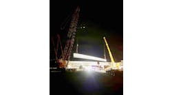
The cross section for each bridge has an 80-ft-wide top slab and 1-ft 4-in.-thick webs. For the haunched spans, the box depths vary parabolically from 18 ft at the pier segment to 10 ft near midspan. The constant-depth approaches are 10 ft deep. The utilities running the length of the bridge are confined within the box to allow for a more aesthetically pleasing structure. The bridges are constructed in balanced cantilever using a gantry to lift the segments from the water. The maximum segment weight is approximately 200 tons.
Construction of the new Hathaway Bridge is scheduled for completion in the fall of 2003. The test piles were driven and analyzed using a statnamic load test and are giving ultimate capacities of up to 5,000 kips (1 kip = 1,000 lb) in some locations. Superstructure construction is under way. About half of the first bridge is in place. The next cantilever to be erected will be the channel span for the first bridge.