In the interior of British Columbia, Canada, the cities of Kelowna and Westbank lie on opposite sides of Okanagan Lake. The lake is 135 km long and, on average, between 4 and 5 km wide. Its maximum depth exceeds 260 meters. The only bridge across the lake is located between Kelowna and Westbank, roughly at the midpoint of the lake, and is one of only a handful of floating bridges in the world.
The original bridge was built in the 1950s, and due to an incredible increase in the number of people living in the beautiful area, by the late 1990s traffic averaged 46,000 vehicles per day, making the three-lane bridge functionally obsolete. After many studies, in 2003 the Provincial Government decided to replace the aging structure with a new five-lane crossing through a public-private partnership (P3) model as a design-build-finance-operate project.
A winning team
The contract, signed in July 2005, involves the finance, design and construction (over a period of three years), operation and maintenance during a period of 27 years and finally the transfer of the structure to the Ministry of Transportation. The winning team used a design developed in the late 1990s by Westmar Consultants as a base design, but modified it to comply with the latest version of design codes and to incorporate construction optimizing changes.
The concessionaire’s team consists of the following: SNC Lavalin (concessionaire and financier); SNC Lavalin/Vancouver Pile Driving (construction joint venture partners); Greyback Construction (pontoon construction); Emil Anderson (road works construction); SNC Lavalin (roads design and design coordinator); Buckland & Taylor Ltd. (bridge design lead and fixed structure design); Aas-Jakobsen AS/Johs. Holt AS (floating structure design); Ben C. Gerwick Inc. (pontoon anchor design); Northwest Hydraulics (wind and wave loading for the floating structure); Trow (geotechnical design, environmental design and quality management); and DMD Electrical (electrical design). With its previous knowledge of the bridge, Westmar took on the role of owner’s engineer for the project.
In order to re-use the existing road infrastructure, the new bridge was located alongside the existing bridge. Also, to minimize the cost of the project, the new bridge re-used the anchors and lower portion of the anchor cables from the existing bridge. This use of common anchors required both bridges to be connected during construction.
Unlike the original bridge, which had a lift span for navigation, the new bridge has a fixed, elevated approach structure with a navigation span on the west side of the bridge. The middle portion of the bridge is comprised of the floating pontoon string, and transition spans are provided from both the west approach structure and the east shore to the pontoons.
Hold steady
Buckland & Taylor Ltd. designed the 300-m-long fixed structure for the new bridge. Because of poor soil conditions in the lake, the west approach structure was designed with lightweight composite steel plate girders with 60-m spans to limit the number of piers and the loading on these piers.
The piers are supported on steel composite piles, which are embedded up to 50 m into the lake bed.
The pile caps for the piers were designed with the soffit above the high water level to ease constructability, but given that Okanagan Lake is a recreational lake, the pile caps were designed with a pier skirt to prevent accidents with swimmers, boaters or equipment getting caught underneath the pile caps. These structures (including the pier skirts) were designed for both ship collision from a barge and ice loading.
Buckland & Taylor Ltd. also designed the two composite steel-plate girder transition spans for the new bridge, and while these spans appear to be simple structures, they are actually quite complex. The structures each span 54 m and are simply supported at both ends, with one end of the girders supported on the floating pontoon string and the other end of the girders supported on a fixed structure. Because of the movement in the floating structure (up and down, north and south, as well as rolling), the transition spans must accommodate significant movements while maintaining the rideability of the roadway surface. The lake level fluctuates by several meters every year (the lake level is regulated for flood-control purposes), so the transition spans must be long enough to prevent significant grade changes in the roadway due to changes in the water level. The pontoons move laterally by approximately 300 mm in a wind storm due to the relatively low stiffness of the anchor cables. In addition, the west transition span had to accommodate additional lateral movement caused by rolling of the pontoons (due to traffic load and wind load) since the elevated structure is approximately 20 m above the lake level. In order to accommodate the roll of the pontoons, the transition spans were designed with a very low torsional stiffness so that they would simply twist with the motion of the pontoon. In addition, the east transition span provides the longitudinal fixity for the pontoon string.
Given that the transition span structures were designed with 6° of freedom, and that the east transition span was designed to fix the pontoon string to the east abutment (including holding back the pontoon string during an earthquake event) in the longitudinal direction of the bridge, the bearing arrangement for the transition spans is very complex.
Flotation device
Due to their combined experience with similar floating bridges in Norway, Aas-Jakobsen and Johs. Holt were part of the design team as subconsultants to Buckland & Taylor Ltd., and together they designed the floating portion of the bridge.
The floating part of the bridge consists of a continuous concrete pontoon approximately 700 m long and 25 m wide. The depth of the pontoon varies from 5.14 m to 7.8 m. The roadway is situated directly on the pontoon top slab over the middle length of the pontoon. Roadway access from the high level west approach ramp is via an elevated deck supported on columns that are integral with the pontoon.
The pontoon design was driven by the need for buoyancy and water-tight compartments. The pontoon was designed with a number of internal walls forming water-tight bulkheads, each arranged such that flooding of two adjacent compartments will not affect the integrity of the bridge. The compartments are formed by a series of internal walls within the pontoon. Typical internal walls range from 150 mm to 200 mm in thickness and heights in excess of 5.4 m. Placing concrete in such thin, tall and heavily reinforced walls was achieved by using self-compacting concrete and developing placing techniques and tools that reduced the risk of segregation and other defects.
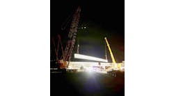
The 700-m-long pontoon was constructed as nine separate parts in a graving dock, or dry dock, and subsequently floated out to the bridge site where they were connected together by means of post-tensioned tendons. After a steep learning curve, the typical construction cycle for a pontoon (90 m long, 14,000 tonnes of concrete, 1,100 linear meters of walls) was established at 70 days, including post-tensioning.
Once several pontoons were connected together at the bridge site, the elevated deck construction started, all while other pontoons continued to be added to the string. In order to control both stresses in the pontoons and overall bridge geometry, water was used inside the pontoons as temporary ballast, placed in such a way as to mimic the load of the final structure and therefore mimic the final pontoon draft. The construction team developed a complex ballasting procedure that involved pumping water in and out of specific locations throughout the construction process. For example, when the concrete decks were placed, an equivalent weight of water was pumped out of the pontoons, often at the same rate that the concrete was added.
Buckland & Taylor Ltd. designed the elevated decks on the pontoons of the new bridge as a lightweight structure with composite steel-plate girders, with relatively short 20-m spans to distribute the weight of the superstructure evenly onto the pontoon and to improve stability.
The nine separate parts of the pontoon were connected together to form a 700-m-long pontoon string using a total of 146 post-tensioned tendons (each using 7- to 15-mm-diam. strands), and 28 high-strength Dywidag bars (44-mm diameter), around the perimeter of the pontoon.
To allow for construction tolerances, and to allow connection of the pontoons and installation of the post-tensioned tendons and the high-strength bars across the joint, it was necessary to design the connection with a relatively large tolerance at the location of the tendons and the Dywidag bars. As such, it was decided to place a steel pipe with an inner diameter of 104 mm in the concrete bulkhead of the pontoons, and then feed the post-tensioned tendons and Dywidag bars inside these pipes. This allowed the steel pipes on the two connecting surfaces to be slightly misaligned, but to still allow the steel across the joint.
Twenty of the existing pontoon anchors were re-used for the new bridge. However, four additional anchors were required for the new bridge. The new anchors were designed by California-based Ben C. Gerwick Inc. as a sub-consultant to Buckland & Taylor Ltd.
The new anchors are reinforced concrete structures with a footprint measuring 6 m by 10 m, and a thickness that tapers from 200 mm to 350 mm, which gives the anchor a total weight of 65 tonnes.
The anchors were jetted 5 m into the lake bed using three massive pumps that were connected to a permanent jetting frame on each of the anchors.
The floating pontoons were connected to the anchors with anchor cables consisting of a heavy sea link anchor chain, which acts like a damper, a 69-mm-diam. lower cable and a replaceable 69-mm-diam. upper cable. The total length of the anchor system varies from 90 m to 240 m.
Due to the fluctuation of the water level on the lake, the floating pontoons were designed with a cable gallery that allows the anchor cable tensions to be adjusted. To obtain a minimum tension in the cables (even during a 100-year return period wind storm), but also to avoid exceeding the capacity of the anchor cables and the anchors, the cables require adjusting on a biannual basis.
Special-needs span
The construction process started in August 2005 with the commissioning of the graving dock on the northwest shore of the lake. Pontoon construction started on January 2006 and the new structure was in service at the beginning of June 2008. At the time of writing this article, the demolition of the old bridge was still under way.
The schedule was extremely tight, requiring steel to be ordered within six weeks of contract signature and pontoon construction to start before the final design was completed. The contractual model, which integrated the design and construction teams, allowed complete coordination and reduced the time between the release of Issue For Construction drawings and placement of concrete onsite to as little as two weeks.
The team integration extended to the future operations and maintenance contractor, who kept a representative onsite during construction and was consulted during the design and construction stages. Life-cycle costs were considered for several elements, such as drainage, expansion joints, deck finishing and electrical and electronic systems. Partnering also was very prevalent with the different subcontractors, at times, blurring the lines between them and the main contractor.
The P3 process for the replacement of the floating Okanagan Lake Bridge allowed the design, construction and operations teams to effectively collaborate in the development of the design of the new bridge.
The uniqueness of the floating bridge required the development of a project-specific design criteria that augmented the Canadian Bridge Code with requirements from the Norwegian and other codes.
The heavily reinforced thin concrete walls of the pontoons required the use of self-consolidating concrete.
The construction team had to be sensitive to the special nature of the floating structure, developing innovative methods and new solutions for the construction process.