Bridges built to accommodate airplane traffic are becoming more common throughout the U.S. Existing airport site constraints have forced the use of runway and taxiway bridges to carry aircraft across roadways, railroads or other facilities. Airside design issues vary significantly from those encountered in the design of traditional highway and railroad bridges. Issues regarding applicable design specifications, bridge geometry, aircraft loading and other Federal Aviation Administration (FAA) requirements need to be addressed by the designer to assure a long-lasting and low-maintenance facility.
A new five-span post-tensioned concrete box girder underpass was recently constructed as part of a $35 million design-build project for the city of Phoenix. The project consisted of reconstructing Taxiway Sierra at Sky Harbor International Airport, which included replacing the taxiway pavement and two single-span reinforced concrete rigid-frame structures. The new 406-ft-long continuous taxiway bridge spans both eastbound and westbound Sky Harbor Blvd. traffic and provides three interior spans for future under-deck use.
Two like Tango
During the planning phase, the city of Phoenix was consulted to determine specific airside and landside constraints and concerns. Through these discussions, the design team identified several structure goals for the Taxiway Sierra Reconstruction project.
First, the client wanted to minimize interruptions to airside and landside operations during construction. Shutting down Taxiway Sierra to reconstruct the bridge would increase congestion on other taxiways. In addition, the falsework and drilling operations necessary to construct the bridge required detours and lane closures that would significantly impact Sky Harbor Blvd. motorists.
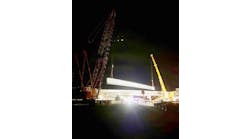
Second, the design team needed to provide an aesthetically compatible, cost-effective and maintenance-free facility. Taxiway Tango Underpass, located approximately 100 ft from Taxiway Sierra, is a cast-in-place, post-tensioned concrete box girder bridge that has required no maintenance during its 15 years of operation. The owner wanted the new Taxiway Sierra bridge to be just as trouble-free and compatible with the adjacent bridge and facilities.
Finally, the design needed to eliminate potential conflict with future facilities. An area beneath the Taxiway Tango bridge was being used for parking, and the owner was interested in using future under-deck areas as revenue-generating facilities.
To meet these goals, the following superstructures types were considered during the type, size and location phase of the project:
- Cast-in-place, post-tensioned concrete box girder;
- Precast, prestressed concrete I-girders; and
- Precast, prestressed concrete box girders.
Steel girders were not considered due to the relatively high cost of steel in the Phoenix area and the perceived aesthetic incompatibility with adjacent concrete facilities. The precast girders offered several advantages, the most prominent being reduced taxiway closure time and ease of construction. Dapped-end variations of the precast girder alternatives also were considered to optimize vertical clearance and minimize impact to future under-deck facilities. The cast-in-place, post-tensioned girder option offered consistent aesthetics with the adjacent box girder bridge, optimal vertical clearance, reasonable construction cost and minimal maintenance. A detailed analysis of the alternatives was performed in collaboration with the city of Phoenix and included the following considerations:
- Cost;
- Taxiway closure time;
- Potential use of under-deck area;
- Constructability;
- Aesthetics; and
- Serviceability.
As a result of the alternatives analysis, a cast-in-place, post-tensioned box girder bridge was selected.
At full strength
The typical bridge section shown in Fig. 1 illustrates how the airside requirements were addressed by the design team. A bridge width of 214 ft was used to meet the taxiway safety area width requirement for a Design Group V aircraft. The structure was designed to maintain full strength across its full width to accommodate service and emergency vehicles, and potentially errant aircraft. Curbs were provided at the edge of each deck to divert drainage and help restrain wayward vehicles. Taxiway centerline and edge lighting were spaced along the deck as needed to meet FAA lighting requirements. Additional conduits were placed within the cross-section for under-deck lighting, future power and communication utilities.
The project design specifications referenced the following documents: FAA Advisory Circular 150/5300-13, FAA Advisory Circular 150/5320-6D, American Concrete Institute (ACI) 343R-95 and the American Association of State Highway & Transportation Officials (AASHTO) Standard Specifications for Highway Bridges. The design criteria specified a design aircraft gross weight of 1.5 million lb, based on a Boeing 747-400 configuration. A vertical force equal to 30% of the design aircraft weight was added to the live load to account for impact, and a longitudinal braking force equal to 75% of the design aircraft weight also was applied to the structure. Load factors from AASHTO were used to establish factored design demands.
ACI 343R-95 effective width provisions were used to distribute live loading to the bridge deck. The 15-in. deck slab was sized for punching shear and flexural requirements. Transverse flexural reinforcement was determined using a wheel load configuration consistent with the gear arrangements for the design aircraft. Drop beams were added at lighting locations to effectively transfer wheel loads to the adjacent girders.
The girder was designed using the distribution factor provisions of ACI 343R-95. The distribution factor was based on the number of girder webs that were located within the landing gear footprint. This distribution factor was verified by using a three-dimensional finite element model that satisfied the refined analysis requirements of the ACI code. The design aircraft was positioned transversely across the full bridge width to determine the extreme live loading effects. Thirty-seven webs with a spacing of 5 ft 11 in. and a total post-tensioning jacking force of 87,800 kips were used to support the design aircraft.
The substructure consisted of four piers and two abutments supported on drilled shafts. Wide columns were used at these piers to transfer the longitudinal braking force. The bridge length required for this project resulted in the use of non-integral abutments. Aircraft surcharge forces acting on the abutments resulted in a 5-ft-thick stemwall and two rows of drilled shafts. Seismic loading did not control the substructure design/detailing because the bridge is located in a low seismic region.
Both an approach slab and anchor slab were used at the ends of the bridge. An approach slab thickness of 20 in. was required to satisfy flexural demands from vertical design aircraft loads. An anchor slab was used between the approach pavement and the bridge approach slab. A 3-in.-wide expansion joint was specified at the end of the approach slab and a doweled expansion joint was provided at the end of the anchor slab.
Several constructability issues were addressed during design. Heavy reinforcing requirements at pier caps, column connections and abutment anchorages required special detailing to avoid congestion and ensure adequate concrete consolidation. Other construction considerations included airside and landside staging/phasing.
Counter point
Designing bridges for aircraft requires several unique considerations when compared to their highway and railroad counterparts. The development of a project design specification, meeting airside and landside geometry requirements, and designing the structural components for the transfer of large aircraft loads are all factors that must be considered during design. Having early discussions with the owner and providing adequate consideration to the type, size and location of the bridge can save time and cost, and will lead to the overall success of the project.