A Veer to the right
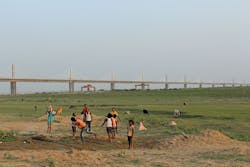
The new Veer Kunwar Singh Bridge, formerly known as the Arrah-Chhapra Bridge, opened to traffic in June 2017 and connects the rapidly growing cities of Arrah and Chhapra in the northeastern Indian state of Bihar.
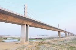
The bridge has a total length of 4.35 km, 1.96 km of which is composed of back-to-back 120-m-long extradosed spans across the navigational channel, making it the new world-record holder for longest multi-span extradosed bridge. The extradosed spans connect to simply supported approach spans on either side of the enormous Ganges River. The new bridge supports two sidewalks and a total of four lanes of traffic; instantly providing a 25% boost to the road-bridge capacity of the state, which has a population of 117 million.
Bihar has been undergoing a massive infrastructure expansion boom in recent years as part of a federal development package to improve the economic outlook for the state, which is India’s poorest in terms of GDP per capita. The package includes several megaproject bridges over the Ganges that are currently under construction or recently completed, with the most significant being the $130 million Veer Kunwar Singh Bridge, in terms of road transport capacity. The project was procured through a design-build arrangement with S.P. Singla Constructions Pvt. Ltd. acting as the prime contractor and McElhanney Consulting Services Ltd. ultimately selected as the prime consultant, responsible for the conceptual and detailed design, erection engineering and construction site support for the extradosed navigation spans.

The 60-m-long spans, composed of single-cell precast box girder segments with inclined webs and internal struts, on the Veer Kunwar Singh Bridge are supported by hammerhead piers on top of caisson foundations.
How it came together
Separately, the 30 spans on the south approach and six on the north approach were designed by an Indian consultant and standardized with 60-m-long spans composed of single-cell precast box girder segments with inclined webs and internal struts. The spans are supported by hammerhead piers on top of caisson foundations. The girder segments were cast in nearby casting yards and erected using the span-by-span method, with an overhead portal crane used to erect segments onto jacks supported by falsework.
The navigation spans were originally designed as variable-depth single-cell box girders, but unlike the approach spans, these were to be cast in place and continuous over the piers, with articulation provided at mid-span. However, after the initial construction had commenced, S.P. Singla approached McElhanney to develop a design for an alternative extradosed system for the navigation spans, which would not only bring several technical advantages, but also provided S.P. Singla with valuable experience in erecting extradosed bridges—a contract requirement for many of the upcoming Ganges bridge projects. Some of the most important benefits of transitioning the navigation span design from the original cast-in-place girder system to the new extradosed system included the additional support of the extradosed stay cables, which permitted the use of smaller segments that could utilize the same outer segment dimensions as the significantly shorter approach spans.
The new adjustable shuttering that would have been required for variable-depth cast-in-place segments would no longer be needed as the extradosed spans used the same outer cross-section as the approach spans, allowing for the reuse of the approach span shuttering, with only minor adjustments to the core forms.
Using the existing casting yards to produce the navigation span segments not only utilized an existing asset, but also improved the quality of the segment reinforcing, forming and casting compared to the cast-in-place alternative, while also permitting covered casting during the monsoon season—a very important attribute for the region. The smaller segments meant more efficient use of materials, significantly reducing the volumes of concrete, steel reinforcement and high-strength deck tendons used in the overall bridge construction. By enabling a lighter overall superstructure, the extradosed stay cables effectively lowered the foundation demands compared to what would be required for a variable-depth girder span, hence considerably reducing the construction time and cost of the piers and foundations.
Once the extradosed segments were cast in the casting yard, they could be erected at a typical cycle time of three days for a pair of segments, approximately three times faster than the alternative cast-in-place construction cycle.
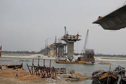
The bridge is founded on 9.5-m-diam. concrete caissons that were sunk 53 m into the fine river sands of the Ganges. Twinned reinforced concrete pier blades were integrally cast on top of the caissons, and with long and thin aspect ratios of 6,500 mm x 850 mm, they were designed to accommodate the longitudinal expansion and contraction of the continuous superstructure while still providing strong resistance for transverse loading. Being twinned, the axial force couple between the blades provides a stiff rotational restraint to the superstructure about the transverse bridge axis, greatly reducing live-load stresses in the superstructure by providing each span close to fixed-fixed end conditions.
The pier blades also are integral with the superstructure pier table to provide a robust connection for seismic demands as well as the construction loads during the free-cantilevering operations. The 8.5-m-long pier tables are cast in place to accommodate the heavy diaphragms contained within, which transfer the combined forces from the spans and the pylons down into the pier blades.
A single plane of stay cables anchored along the bridge centerline, between two central traffic barriers, support the superstructure at five stay-anchorage segments along the length of each cantilever. The five cables are arranged in a harp configuration and project 19˚ from horizontal. They consist of 61 continuous strands threaded through a central saddle cast into the pylon. The longest and shortest cables were stressed to 38% and 43% of the GUTS during installation, respectively; the longest cables see slightly more live-load stress and thus require more reserve capacity.
The extradosed pylons rise 18 m above the deck and are kept narrow, at only 1,000 mm, using cable saddle pylon anchorages to avoid overall widening of the bridge deck. The contribution of the pylons to live-load resistance is minor; their longitudinal dimension, 2.5 m, makes stiffness negligible relative to the 3.4-m-deep superstructure, so the stay cables are essentially dominated by permanent loads. The pylons are relatively tall for an extradosed bridge; the height is approximately span/7, compared to the more commonly employed span/10. This extra pylon height was required to produce a greater overall effective structural depth by placing the stay saddles further up from the girders. Such an arrangement was desired over the alternative of increasing the girder depth and thus changing the box girder’s outside dimensions relative to the approach spans.
The superstructure girders are similar to the approach spans—composed of single-cell precast box girder segments with inclined webs and internal struts—but utilized variable elemental thicknesses to accommodate for the higher demands near the piers while still maintaining a single set of outside dimensions for each girder segment. The girder bottom flange thicknesses varied from 700 mm at the piers to 300 mm at mid-span, whereas the girder web thicknesses ranged from 550 mm at the piers to 350 mm at mid-span. In order to maintain nearly a constant weight for all girder segments for transportability, the girder segment lengths varied from 2.45 m at the pier to 3.07 m at mid-span.
Continuous superstructures are desirable for durability and material efficiency but as the continuous length increases, demands also increase on the integral piers due to the effects of thermal expansion, creep and shrinkage in the superstructure. An appropriate balance was achieved at three continuous spans—a total length of 360 m—an arrangement that imposed acceptable deformation demands on the integral pier blades while achieving a maximum continuous superstructure length. The expansion joints, located at the connections between these three-span-continuous pier units, presented a difficult design problem, because a simple hinge would overload the extradosed cantilevers and allow significant downward creep displacements. To avoid this scenario, the joint needed to provide continuity for bending moments and shears, while still permitting free longitudinal movement. These objectives were achieved by employing two innovative compact steel continuity beams that were telescoped inside the superstructure girders near the end of cantilever erection, and when rolled forward and spliced at cantilever completion, provided sufficient stiffness to effectively create a continuous span with structural efficiency similar to the typical adjacent girder segments. Fitting the 1.5-m-deep beams inside the 3.4-m-deep superstructure required careful design of the bearing diaphragms to ensure that the large shear forces could flow from the inclined webs of the superstructure to the bearings points on the continuity beams, and vice versa. The stiffness and length of the internal continuity beams was selected to reduce the anticipated long-term angle break at mid-span, due to creep and shrinkage, to within acceptable limits.
At 4.35 km, the bridge is the new world-record holder for the longest multi-span extradosed bridge.
From the very wet to the very dry
The climate in Bihar varies drastically between the monsoon season flooding and the extreme heat of the dry season. The monsoon season during construction caused dramatic changes in the riverbed; the water level increased by as much as 11 m, producing a significant design scour of 30 m below the caisson cap; while the river breadth expanded from 300 m to up to 5,500 m, and the positions of the deepest portions of the channel routinely shifted year to year, severely disrupting construction transport activities in the riverbed. The dry season, on the other hand, created problems with geometry control in the open casting yards by exposing the freshly cast segments to the intense sun and ambient air temperatures. Despite attempts to uniformly cure the precast girder segments, differential shrinkage was noticeable between the top and bottom flanges. In storage, the top flange was subjected to sun and intense drying while the bottom flange was often excessively close to the ground. Water sprayed on burlap sheets covering the top flange evaporated quickly and thus required constant watering, which was intermittent in practice. The magnitude of differential shrinkage between the top and bottom flanges was found to be directly linked to the weather following the casting work. The segment top flanges were found to shrink much more than the bottom flanges, which manifested into an upward curl in the erected cantilevers.
To counter this effect, among other influences, corrective measures were employed during segment erection. Typically, a series of six shims were placed along the segment top flange prior to epoxying to alter the angle of the next segment. The shim thickness varied depending on the misalignment severity in the projected geometry. In a few cases, where the shimming was not sufficient to correct the cantilever projection, a wet-stitch was employed, which involved setting the new segment on the ideal profile but separated from the previous segment by a narrow gap, which was filled with fine aggregate concrete. The gap width was set by variable thickness HDPE blocking installed at the segment top and bottom flanges. By manipulating the thickness of the blocking, the desired vertical and transverse profiles were achieved. While forming the segment shuttering and setting up the concrete pumping equipment took some time out of the schedule, wet-stitches were found to be a reliable method of resetting the geometry and establishing the projections back to a desired theoretical path to the mid-span.
The new Veer Kunwar Singh Bridge connects the rapidly growing cities of Arrah and Chhapra in the northeastern state of Bihar in India.
Fast way about it
The construction team completed the bridge in only 2.5 years, which is a record construction time for similar extradosed or cable-stayed bridges in India, where construction times often exceed 10 years. This was despite the fact that construction was hampered by local riots and criminal activity, mostly antiquated equipment, and the extreme climate conditions. Ultimately, the expertise McElhanney provided to S.P. Singla and local contractors has allowed these companies to develop important experience in the construction of megaproject bridges, which will be invaluable as the region continues to advance its infrastructure. Additionally, the project used 90% locally sourced materials and employed hundreds of local workers during the construction, providing a significant stimulus to the struggling local economy.
Now that the Veer Kunwar Singh Bridge is complete, it brings significant relief to the river and traffic congestion in the capital city of Patna, which had previously been the nearest crossing point, and in suit, the bridge saves over three hours of travel time across the Ganges for the more than 30 million people living in western Bihar. It is hoped that these improved travel times and the potential for enhanced commercial growth will continue to improve the local economy and help bring prosperity to Bihar.