Replacing traditional 2-D plans with 3-D digital models on the Iowa I-80/380 BIM pilot project
The era of 2-D paper plans for roads and bridges may be coming to an end.
As design technology continues to advance, pilot projects across the U.S. are proving that these printed sheets are no longer always needed. Just as CAD replaced hand-drawn plans decades ago, a new technology is emerging for infrastructure planning, design, construction, and asset management: building information modeling (BIM) for infrastructure.
When used well, these information-rich 3-D models can produce more efficient and sophisticated designs and ultimately lead to cost savings, as well as long-term benefits over the life of an asset. But as with any new approach, there are growing pains.
“We’re introducing a new technology that we all need to learn,” said HDR’s Todd Horton, who oversees bridge projects in Nebraska and Iowa. “Once we break through that, I think it’ll definitely be an advantage, both from a cost and from a construction standpoint, likely cutting down on construction cost overruns ... Some things you really can’t see, or that you miss in 2-D, such as a conflict between a utility pipe and a traffic signal conduit, become apparent in a 3-D model. It’ll likely minimize the up-front costs of the engineering, and also the construction costs.”
The Iowa DOT (IDOT) recently used a major interstate project as a pilot project for using BIM in design, part of its eventual goal to use the technology in all projects. The Iowa I-80/I-380 reconstruction provided valuable insights into the benefits of regularly using BIM—and the steps required to make that a more broad-based reality.
“Our design group has made a decision that they’re going digital,” said Ahmad Abu-Hawash, chief structural engineer for IDOT. “The long-term hope would be to be able to use BIM from the first phase of conceptual design all the way through asset management.”
HDR developed BIM models for three bridges on the interchange project, a major reconstruction of a high-traffic section of interstate. As the project progressed, IDOT decided to use one of the packages with the model as the legal document, where the BIM information was the signed and sealed contractual deliverable, replacing the traditional 2-D plan set. This allowed IDOT officials to evaluate the use of BIM during the construction phase and gain experience in working with contractors on using the technology.
“The whole purpose was to really discover what the state of the art is, because until you do it, you really don’t know,” Horton said.
BIM has been used successfully for years in the vertical building industry, but BIM for infrastructure is also revealing exciting possibilities for transportation projects. Improved design accuracy, early identification of constructability issues, better visualization, and eventual asset management capabilities are all expected benefits.
The Project
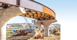
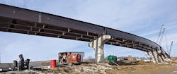
The I-80/I-380 interchange northwest of Iowa City is one of the busiest traffic segments in Iowa. It was targeted for a $450 million widening and reconstruction of its ramps, which have been the site of multiple accidents and rollovers. HDR had been involved with the project from the early planning stages and began providing final design services for the interchange’s bridges in late 2016.
IDOT selected the I-80/I-380 reconstruction as a BIM pilot project based on schedule and complexity. The bridges contained a variety of challenges, including curved steel girder design, discontinuous girders, complex superelevation transitions, inspection walkways, and highly aesthetic substructure elements. The complexities allowed IDOT and HDR to better evaluate the capabilities of the software used and understand the advantages of creating a BIM model during design.
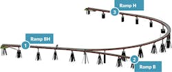
The three flyover bridges modeled as part of this project were:
Ramp BH: a single-unit bridge, 799-ft-long steel plate girder superstructure curved at each end of the bridge supported by skewed concrete T-Piers and includes one gore area accommodating the Ramp H & B diverging exit.
Ramp B: a single-unit 647-ft-long curved steel plate girder superstructure supported by concrete T-Piers.
Ramp H: a three-unit, 2,845-ft-long curved steel plate girder superstructure supported by concrete T-Piers.
Key Software Takeaways
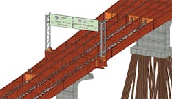
The design tested the limits of available software. Designers modeled the bridges in two programs: They first used Bentley’s OpenBridge Modeler V8i (OBM) to create the primary bridge elements at a low level of detail, then added details to the model with ProStructures V8i.
Throughout the model development, HDR designers stayed in contact with Bentley to discuss what worked well and what could be improved. A number of proposed efficiencies were identified and work-arounds developed.
Modelers found the programs’ usefulness depended on the stage of design:
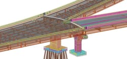
OBM was most useful during the early stages of design, when a high level of detail was not necessary. Templates and tables sped modeling on sections with similar components, and they allowed the model to be quickly updated after design changes. As parameters of an element changed, the model automatically updated itself. But more complex elements posed a problem. Elements such as pier caps and columns, stub abutments, and diaphragms could not be modeled in OBM to the high level of detail required. These elements were later added in ProStructures.
ProStructures was much more flexible, but also more time-consuming and difficult to update. Elements in ProStructures are not tied to templates or tables, and that gave users more flexibility in their design. Designers were able to create nearly all features of the three bridges, aiding in clash detection and visualization. But it also slowed the process of updating the model. Modeling at a high level of detail required a significant time investment.
Model Delivery
Creating a highly accurate, detailed model was an important milestone for designers. But in order to be useful as a construction document, the model needed to include all of the information to construct that bridge. That includes plan notes, tables, details for vendor-supplied items, and more.
“Instead of providing a PDF of the sheets, we included that extra information as links within the model itself,” said HDR Bridge Engineer Grant Schmitz. “That allowed us to incorporate everything into the model.”
Adding information was not the only concern of designers. Some information was also superfluous.
The information provided by default in the modeling software included important data such as material properties, dimensions, and construction notes. However, much of the displayed information was also irrelevant, duplicative, or potentially misleading. To add clarity, the element properties were modified to be more concise and provide only the needed data. To achieve this, designers used two additional programs: i-Model Transformer and MicroStation CONNECT.
The read-only BIM model of Ramp B was the primary contractual signed and sealed deliverable and included a complete list of all linked files, instructions to access, and recommended software. An information hierarchy was also created in case of a discrepancy between files.
Contractor Use
The original plan was to create models for all three bridges as information only, to evaluate BIM software’s capabilities while still providing traditional 2-D plan sheets for each bridge. That way contractors could refer to the models frequently during construction and provide feedback on their use. It became evident, however, that the use of the model would be very limited when provided alongside a 2-D plan set. So IDOT decided to use BIM rather than 2-D plans as the primary design contractual deliverable for Ramp B. This change allowed IDOT to gather feedback from contractors on their experience and gave contractors an opportunity to gain experience in this new method. Potential bidders could receive free training on Bentley View, and the selected bidder chose to buy a license for ProStructures after being awarded the construction contract.
The contract for the three bridges was awarded on July 31, 2018, for $38.2 million. Early feedback has centered on difficulties extracting information from the model. Subcontractors and fabricators had little experience working with the software provided and were not able to fully use BIM. Often, this left the prime contractor responsible for extracting the relevant data for them. In some cases this involved creating 2-D sheets from cut sections of the model.
Working with tablets in the field has also proven difficult. This is not only a result of conditions inherent with working outdoors, but also with software limitations, as it was developed specifically for mobile devices.
Although there have been some early challenges associated with the use of a BIM deliverable during construction, the process does show promise. As expected, the model has been used repeatedly for visualization, particularly in highly congested areas of rebar. The model has also been used to create formwork for elements with complex geometry.
A Historic Shift
The goal of this project was to put an emerging technology to the test, find out where it improves on existing methods, and where it can be improved itself. To that end, IDOT and HDR learned valuable lessons about the capabilities of BIM software and what is needed to take best advantage of the technology on current road projects:
New workflows are needed for the use of BIM rather than traditional design. Iowa aims to eventually use BIM and models as the legal document routinely in its projects. The department is planning to start using OBM and ProStructures internally, “developing new workflows and determining our 3-D deliverables,” said IDOT Automation Engineer Annette Jeffers. Among considerations are what specific information must be included in a deliverable and at what level development models must be created.
BIM improved interdisciplinary coordination. Some details of roadway conflicts and coordination were easier to track using BIM. On the Iowa project, that meant existing, interim, and final grading could be incorporated into the model, along with existing and proposed roadway alignments.
Quality control is a much different challenge in a 3-D model than a 2-D deliverable. “Checking a massive model has its own challenges,” Horton said. It is important to have senior, expert reviewers who are also knowledgeable in the new software, or a clearly defined process that makes it clear what reviewers need to look at in a model as opposed to traditional plan sheets.
Other benefits are farther off, but early adopters such as IDOT and HDR’s designers can already see them on the horizon:
Better information sharing is coming. An ongoing effort to create a new open data standard for BIM will eventually allow operability between software programs. That will radically improve information sharing and increase the ability for fabricators and others to easily find and access relevant information required for their specific work. “That’s when we’re going to see most cost savings in terms of the model versus traditional plans,” Horton said.
A 3-D model means less information loss from designer to contractor. As contractors become more familiar with software and models, designer intent will be much clearer. A 3-D model allows you to see exactly what designers are imagining.
Over time, BIM for infrastructure will be faster and cheaper. “Initially, the time investment in BIM and 3-D models is probably going to be a little higher,” Horton said, “but over time, I think you are going to see some cost savings by not having to go through sheet development, because that is a process in itself.”
As the industry continually looks for new efficiencies and better approaches, pilot projects such as these are key to understanding what’s possible. A major process change such as this will not happen overnight, but all of those involved in this project are confident that BIM will become the standard for infrastructure design in coming years. A decade from now, traditional 2-D plans may be as quaint as hand-drafting.
“Twenty, 30 years ago we used to do everything on paper,” Abu-Hawash said. “Then CAD came along and everybody said, ‘That’s crazy, why would you want that?’ Now nobody remembers drafting on paper.”