Ready to fill in
Hollow-core concrete columns have been used for very tall bridge columns in seismic areas including New Zealand, Japan and Italy. Hollow-core cross-sections reduce the mass of the column, which reduces the bridge self-weight contributing to the inertial forces during earthquakes.

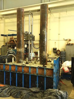
HC-FCS columns were fabricated and tested at the Missouri University of Science and Technology laboratories.
Hollow-core columns also reduce the required foundation dimensions, thereby substantially reducing construction costs. These advantages have increased the use of hollow-core columns instead of similar solid members. In addition, the hollow-core columns are more sustainable than the solid cross-section columns, as they use less concrete.
Researchers investigated the seismic behavior of hollow-core concrete columns that have two coaxial layers of reinforcement and transversal reinforcement connected using a significant number of cross ties placed throughout the column wall thickness. While such columns exhibited a ductile behavior, they require extensive manpower and have not been a cost-effective construction option. Other researchers investigated hollow-core concrete columns that contain one layer of longitudinal reinforcement within the column wall thickness to reduce the required manpower. Such columns displayed brittle behavior with low displacement ductility and hence are not appropriate for use in high seismic regions. This brittle behavior occurred because of the concrete spalling and longitudinal reinforcement buckling.
Looking at four
Recently, the Missouri University of Science and Technology investigated the seismic behavior of an innovative hollow-core bridge column. This column consists of a concrete wall that is sandwiched between two generally concentric items: an outer fiber-reinforced polymer tube and an inner steel tube producing what is called hollow-core FRP-concrete-steel columns (HC-FCS). Figure 1 shows the typical cross-section of an HC-FCS column. The HC-FCS column combines and optimizes the benefits of all three materials: FRP, concrete and steel. The steel tube acts as a stay-in-place formwork, as well as longitudinal and shear reinforcement. The steel and FRP tubes act as continuous confinement to the concrete core, which increases the column’s ductility and strength compared to conventional hollow-core columns. Furthermore, the concrete core delays the local buckling of the steel tubes.
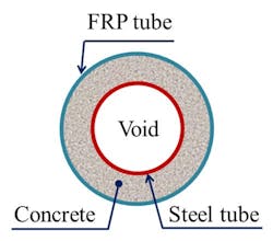
Figure 1. A typical cross-section of an HC-FCS column.
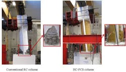
Figure 2. The failure result of high lateral drift at 15.2% (left) and 10.9% (right).
The HC-FCS column requires 90% less construction time and 75% less manpower than the corresponding conventional RC column. The HC-FCS column uses 60% to 75% less concrete material compared to the conventional RC column having a solid cross-section because it has a hollow core. The HC-FCS column also requires reduced freight cost when implemented with precast construction. Due to the protection afforded by the corrosion-free outer FRP tube and concrete core, the HC-FCS column is anticipated to have high corrosion-resistance.
This research investigated the first large-scale HC-FCS columns under seismic loading and compared the results with those of the conventional RC column. The investigated HC-FCS columns were constructed using over-the-counter filament-wound FRP tubes with fiber direction of ± 53°, 4-in.-thick concrete walls and thin steel-tube thickness with a diameter-to-thickness ratio of 64.
Four large-scale columns were tested as free cantilevers under both constant axial compression load and cyclic lateral loading. The first column was a conventional RC column having a solid cross-section and the other three columns were HC-FCS columns. Each column had a circular cross-section with an outer nominal diameter of 24 in. The typical cross-section of the HC-FCS columns had an inner nominal diameter of 16 in. Each column had a height of 80 in. The lateral load was applied at a height of 95 in. measured from the top of the footing, resulting in a shear-span-to-depth ratio of ~ 4.0.
The RC column had a longitudinal reinforcement of eight longitudinal bars of size No. 7 corresponding to approximately 1% of the concrete cross-sectional area and it had a transversal spiral reinforcement of bar No. 4 with a spacing equal to 3 in. corresponding to a volumetric reinforcement ratio of 1%. The concrete cover beyond the spiral reinforcement was 0.5 in. For the HC-FCS columns, the FRP tube thickness, steel tube thickness, and concrete wall thickness of the HC-FCS columns were investigated during this research. The investigated FRP tube thickness was 0.125 in. or 0.375 in., the investigated steel tube thickness was 0.25 in. or 0.50 in., and the investigated concrete wall thickness was 4 in. or 5 in. The inner steel tube of each of the HC-FCS columns was extended inside the footing and the column loading stub using an embedded length of 25 in. representing 1.6 times the steel tube diameter. The FRP tube was stopped at the top surface of the footing and at the bottom surface of the column’s loading stub. The steel tubing of all of the HC-FCS columns were hollow. None of the HC-FCS columns included any shear or flexure reinforcement except the steel tube.
Constant axial load of 110 kips representing 5% of the RC column axial capacity (AC) was applied to each of the columns. AC was calculated according to ACI 318-14. After applying the axial load, cyclic lateral loading was applied in a displacement control using two hydraulic actuators connected to the column’s loading stub in one end and the strong wall at the other end until the column’s failure.
The HC-FCS columns displayed better seismic behavior than the conventional solid cross-sectional RC column. The HC-FCS column exhibited high lateral drift reaching to 15.2% while the RC column failed at a lateral drift of 10.9% (Figure 2). The lateral drift of each column was obtained by dividing the lateral displacement by the column’s height of 95 in. The HC-FCS, in general, failed gradually with concrete compression failure, local steel tube buckling and FRP rupture. The RC column failed by rebar rupture, and the moment capacity dropped more than 20% after that. At this stage, the RC column suffered severe damage in the form of concrete crushing and spalling, buckling and fracture of longitudinal rebars, and excessive lateral deformation of the spiral reinforcement. The ultimate moment of the HC-FCS columns was at least 1.23 times that of the conventional RC column. The HC-FCS columns dissipated higher energy, reaching to 1.9 times that of the conventional RC column.
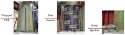
Figure 3. The process of repair to an HC-FCS prior to retesting.
Repair of the HC-FCS columns was easy, fast and effective. During this research, after testing the HC-FCS column, it was repaired and retested using a loading regime similar to that of the virgin column (Figure 3). The repair started with removing all big chunks of crushed concrete. Generally, concrete chunks having diameters of up to 3 in. were removed; then a vacuum was used to suction out the smashed concrete and dust. Three layers of unidirectional glass FRP (Tyfo SHE-51) were impregnated with two-component S-epoxy and wrapped around the site of FRP rupture in approximately one hour. A heat chamber using Sonotube paperboard was installed around the wrapped FRP and the temperature was raised to 120°F using a heater. The temperature was measured and kept constant for four hours to ensure glass FRP curing according to manufacturer recommendations. Grout injection was applied using low pressure to replace the damaged concrete chunks in about one hour. The total time of the quick repair was six hours.
The repaired column failed by FRP rupture and achieved high lateral drift of 13.2% before the failure. The quick repair of the HC-FCS column using FRP wrapping achieved 95% of the virgin column’s moment capacity and 61% of the virgin column’s stiffness. The repaired HC-FCS column had remarkable results compared to the conventional RC column where it achieved 117% of the RC column’s strength and 70% of the RC column’s stiffness.
More of a crash cushion
Accidents can have serious repercussions with regard to both human life and transportation systems. Many vehicle collision events involving bridge piers have been reported throughout the U.S. Approximately 15% of bridge failures reported in the U.S. were the result of truck collisions. This research investigated numerically full-scale HC-FCS columns under vehicle collision using LS-DYNA software (Figure 4). The dynamic behavior of the HC-FCS columns was compared to the dynamic behavior of the conventional RC column under vehicle collision. Each column had an outer diameter of 5 ft and a height of 25 ft with a span-to-depth ratio of 5. The soil depth above the top of the footing was 40 in. Both the RC and HC-FCS columns were designed to have the same moment capacity. The longitudinal steel reinforcement of the RC column was 24 longitudinal bars of size No. 11 representing 1.25% of the concrete cross-sectional area. The RC column’s hoop reinforcement was five longitudinal bars of size No. 5. The outer FRP tube thickness of the HC-FCS column was 0.3 in. The outer diameter of the inner steel tube was 3.3 ft and its thickness was 0.25 in. The diameter-to-thickness of the steel tube was 157. Each column was collided with three different velocities of 70 mph, 50 mph and 20 mph. The vehicle mass was 18 kips. The peak dynamic force (PDF) was calculated and compared for each case.
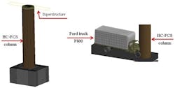
Figure 4. LS-DYNA software rendering of full-scale HC-FCS column vehicle collision testing.
The PDF values of the HC-FCS columns were lower than those of the RC column by approximately 28-39% when they were collided with vehicles having velocities ranging from 50 mph to 70 mph. This reduction in the PDF would save lives and reduce the column’s damage during accidents. The PDFs of the HC-FCS and RC columns were approximately equal when they were collided with a vehicle having a velocity of 20 mph. Concrete spalling occurred during the vehicle collision with the RC column because of high local strains. However, the FRP tube in the HC-FCS column protected the concrete from spalling and increased the ultimate compressive strain by approximately five times that of the RC column. R&B