“High” time for a change
The Smith Avenue Bridge, known as the High Bridge, spanning the Mississippi River in St. Paul, Minn., consists of three continuous tied steel arch main spans with steel multi-girder approach spans.
Originally constructed in 1987, the main spans consist of a 502-ft full arch (Span 4) and two half arches (Span 3 and Span 5) on either side of the full arch, measuring 282 ft 3 in. and 241 ft 9 in, respectively.
Due to deteriorating bridge deck conditions, comprehensive rehabilitation including complete replacement of its original concrete deck was deemed necessary by the Minnesota DOT (MnDOT), the owner of the bridge. MnDOT tasked AECOM with the rehabilitation design of the bridge, which included the development of a deck replacement sequence for the arch spans.
The arch spans consist of two arch ribs spaced transversely at 36 ft. The arch ribs are built-up steel box sections, with a larger box section for the main portion of Spans 3 and 5, and a smaller box section for the remainder of Spans 3 and 5 and all of Span 4.
The arch spans are tied by prestressing tendons connecting the arch at the exterior piers to points near the crown of the main span, leaving a short section of arch rib near the main span crown without a tie present. The tie member is comprised of a wide flange section on its side in addition to the prestressing tendons. One tie member is present for each arch rib and runs from the exterior pier to the crown, resulting in four tie members in total. Although structurally connected, the wide flange section served primarily as a means to allow for original construction of the bridge, and a support for the prestressing tendons prior to stressing. Each of the four tendons comprising each tie consists of 27 0.5-in.-diam. prestressing strands. The tendons are encased in a 4-in.-diam. steel pipe, which was grouted following final stressing of the tendons. The tendons pass through the columns via pipe sleeves allowing the tendons to move independent of the columns.

Known locally as the High Bridge, this structure was originally erected in 1987, and consists of a 502-ft full arch span and two half arches, coming in at 282 ft 3 in. and 241 ft 9 in., respectively. The Minnesota DOT flagged this bridge for rehabilitation and deck replacement.
Ready to proceed
Due to the availability of feasible detour routes, deck replacement was planned using a full closure of the structure. With this in mind, a re-decking sequence that worked in reverse of the original construction, with modifications for constructability, was developed. The four tendons comprising each tie were sequentially stressed during the original construction as the superstructure steel was constructed and concrete placed to limit the stresses within the arch rib to the allowable limits. Accordingly, sequential de-stressing and re-stressing of the post-tensioned tendons were incorporated in the construction steps. Three-dimensional Finite Element Analysis (FEA) involving staged construction analysis was conducted utilizing provisions of the AASHTO LRFD Bridge Design Specifications (2014) to investigate the stress state of the arch spans throughout all stages of construction.
For this project, MnDOT elected to use a construction manager/general contractor (CM/GC) delivery method. This allowed for coordination between the designer and contractor throughout the design process to ensure that the construction sequence and methods assumed for analysis matched those ultimately used by the contractor in the field. This helped to ensure that the live loads assumed for analysis would capture the actual vehicular loading that would be used in construction.
The vehicular construction loading used in the FEA consisted of two vehicles, a tri-axle dump truck (assumed as MnDOT’s SU4 Legal Load) and a Cat 335F LCR excavator equipped with a slab crab. Shielding load of 5 psf was applied to all deck sections. Uniform construction load of 20 psf was applied on all remaining deck areas in a given removal step per AASHTO Guide Spec for Bridge Temp Works. The load factor for these loads was taken as the construction live load factor as specified in AASHTO 2014.
The initial concrete deck removal sequence is shown in Figure 1, where the deck portions are numbered in the order of their removal. It would likely be assumed that no overstress would be anticipated during the proposed sequence, based on the assumption that no overstress occurred during the original construction. Initial analysis results, however, showed significant overstress in the arch ribs and spandrel columns subjected to combined axial and bending force effects. The maximum demand-capacity ratio for the arch ribs was about 1.1 near the crown under the combined action of axial compression and flexure, and it occurred after removal of the first pair of tendons at the initiation of the deck removal sequence, when the construction vehicular loading was enveloped for the entire deck, assuming two crews were present for the removal of deck areas 1 and 2 in the next step.
Accordingly, the construction sequence was modified to prevent overstress in the arch ribs and the spandrel columns. The modified deck removal sequence is shown in Figure 2 where the deck portions are numbered in the order of their removal. As can be seen from Figures 1 and 2, the deck areas were reconfigured such that two bays at the crown of the main arch (area 1D) were removed first after removal of the first pair of tendons, and only one crew of construction vehicles was present on the deck to remove this area. This limited the amount of load near the crown of the arch due to the heavy construction vehicles and thus helped to eliminate the overstress in the arch rib.
The deck placement sequence generally followed the original deck construction sequence. The deck removal sequence included removal of two pairs of tendons on each side of the bridge. During the deck placement sequence, MnDOT wanted to have the opportunity to inspect the removed pairs of tendons, and decide if all four tendons needed to be replaced, as only two of the four needed to be removed for deck replacement. Accordingly, the FEA included cases for either replacement of only the required two tendons, or all four tendons. Ultimately, the decision was made to replace all the tendons within each tie.
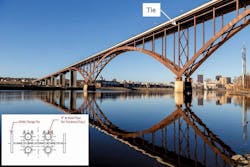
The tie member (highlighted) designed for the Smith Avenue Bridge is comprised of a wide flange section on its side in addition to prestressed tendons. A tie member is present for each arch rib.
Limitations on vehicle movements
Limitations were imposed on the location of the construction vehicles to prevent overstress in the superstructure primary members. Initial analyses allowed all vehicles to be centered over a given arch rib, thus maximizing forces for a given arch rib and spandrel columns. Within subsequent analyses, the movement of the tri-axle dump truck was restricted to the longitudinal centerline of the bridge between the two arch ribs, with a tolerance not exceeding 5 ft on either side of the centerline of the bridge. This allowed the truck load to be shared between the two arches. Similar to the truck, the movement of the Cat 335F LCR excavator load was limited to the center of the bridge for the barrier and the overhang removal, as this removal was completed by an all-terrain crane with a total weight less than the excavator. However, the excavator was located over a given arch rib during the removal of the interior deck portions. At the request of the contractor, a smaller Cat 308 excavator also was included in subsequent analyses to aid in removal of cut deck sections. This excavator was centered over the given arch rib to assess the worst-case loading for the arch. As discussed during the preliminary sequence, the highest demand-capacity ratio in the arch rib was observed after removal of the first pair of tendons when the equipment loads were enveloped over the entire structure. During the modified sequence, no construction vehicular load was allowed on the deck during the tendon removal operation to prevent the overstress in the arch ribs observed from the preliminary sequence. During the deck placement sequence, only the tri-axle truck load was used as a construction vehicle.
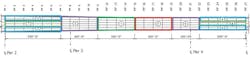
Figure 1. The initial deck removal sequence.
Innovative strengthening
A demand-capacity ratio exceeding 2.0 was observed in shear for the interior pier bearings (at the bases of the main arches), after removal of deck area 2D and 3D. This high level of overstress was determined to be the result of the imbalance of dead load present on the side spans without the deck on the majority of the main span. Additionally, once the deck in areas 2D and 3D was removed, the heavy construction equipment also moved to the side spans to begin removal of areas 4D and 5D to further increase the load imbalance on the side spans. This resulted in a high amount of shear within the interior pier bearings during construction (note that the bearings normally exhibit relatively small amounts of horizontal shear in the as-constructed condition). The capacity of the bearings is controlled by the capacity of a steel pin connecting the arch rib bottom plate to the sole plate. The pin is internal to the bearing and is thereby inaccessible. Thus, a strengthening measure was required which would allow the shear forces to bypass the bearing altogether. This was done by means of a steel system anchored to the concrete pedestal.
The strengthening measure consisted of wide flange beams circumscribing the arch rib bottom plate, and anchored to the concrete pedestal in the longitudinal direction of the bridge. This strengthening measure was pre-tensioned using threaded bars and shimmed to bear against the bottom plate of the arch rib. This ensured that any shear force from the arch rib would be transferred to the pedestal without any displacement occurring within the existing bearing. This also led to the strengthening being designed for the full applied load, conservatively assuming no sharing of load between the strengthening and existing bearing. Following construction, the strengthening measures were adjusted to leave a small gap between the arch base plate and the strengthening, and left in place in the final condition to serve as a catch system should the existing pin ever fail.
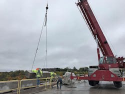
At the location of the de-tensioning device, the grout was exposed 8 ft from the face of each adjacent column face to inspect its quality and then the tendon was jacked up (or down for the lower tendons) to make room for the de-tensioning clamp to be attached to the tendon. A jacking force of approximately 50 kips was required to lift the tendon by about 10 in. Finally, a hydraulic jack was used to release the force in the tendons which was visually confirmed by displacement of the strands. Once the strands were displaced, indicating complete de-tensioning, the strands were cut and the tendon removed.
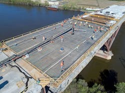
To date, the bridge deck has been replaced along with all prestressed tendons. The concrete barrier and overlay also has been placed on the structure. Moreover, the displacement and strain measurements at different stages of construction matched well with the FEA results, verifying the accuracy of the FE model.

Figure 2. The modified deck removal sequence. Note how the deck areas were reconfigured so that two bays at the crown of the main arch were removed first after removal of the first pair of tendons.
What was learned
As the results of the construction analyses showed, rehabilitation can present a critical loading case for complex superstructures such as the High Bridge. Detailed sequential analyses offer a means to assess construction conditions and develop construction methods to ensure that overstresses within the superstructure do not occur during the construction process. The use of the CM/GC process facilitated an effective and efficient means to develop a detailed construction procedure for incorporating into the final plans and match the sequence during construction. This process also greatly simplified construction submission review processes from what would normally be encountered for a project of this complexity. The bridge is now successfully open to traffic.
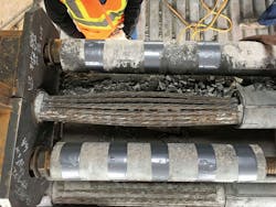
The tendons are encased in a 4-in.-diam. steel pipe grouted following final stressing of the tendons—which pass through the columns via pipe sleeves.