Eastbound span of signature bridge crossing northwestern Florida’s Pensacola Bay will soon be open to traffic
As part of a design-build team with Skanska, WSP USA designed the new Pensacola Bay Bridge, which carries traffic along Rte. 30 (U.S. 98) from the city of Pensacola to Gulf Breeze.
The bridge is a major east-west transportation corridor, a primary hurricane evacuation route and a popular roadway for travelers on their way to Pensacola Beach along the Gulf of Mexico.
The new 3-mile-long structure is replacing a functionally obsolete and structurally deficient bridge that will be removed after the new one is built. The $400 million project is being undertaken on behalf of the Florida DOT (FDOT).
The bridge is being constructed in very challenging geotechnical and marine site conditions, across an open, exposed bay. Its unusual length brings with it challenging ship impacts and hydraulic design requirements.
Design work began in August 2016, and construction of the eastbound span began in the spring of 2017. Attention will soon turn toward the construction of the westbound span bridge, which is scheduled for completion by the summer of 2020.
Landmark design
The original Pensacola Bay Bridge, which first opened to traffic in October 1960, provided four travel lanes and narrow shoulders that created constant congestion problems for traffic that reached 55,000 vehicles per day. To accommodate increasing traffic demands, FDOT called for construction of a new two-span bridge to the west and parallel to the existing structure.
Each span will provide increased traffic capacity through three 12-ft-wide travel lanes, alongside 10-ft-wide inside and outside shoulders. Each span also accommodates pedestrian and bicycle traffic with a 10-ft-wide multi-use path separated from motorized vehicle traffic by a barrier wall.
While pedestrian paths on bridges are common, the use of paths on both sides of the bridge is rather unusual. The decision to provide dual pedestrian paths was driven by strong community involvement in the design process. These paths will feature scenic overlooks and shade structures in addition to educational plaques and other features selected by the community to highlight the local area and history, encouraging walkers and cyclists to explore the bridge and enjoy the journey from shore to shore.
The project also includes reconstruction of the highway approaches to the bridge and improvements to public facilities in the Gulf Breeze Wayside Park.
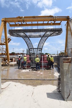
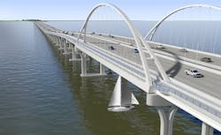
The design provides the bridge with several landmark aesthetic features, including a wishbone tied-arch main span and multi-color aesthetic lighting that creates a ribbon of light across the bay. The arches are designed to maximize the visual impact from all perspectives while also being durable and easily maintained. The architectural details of the tower-supported shade structures and piers mimic the arch’s wishbone, providing scenic views from both the low- and high-level segments of the bridge. Lighting, railings and surface details accentuate the architecture.

One key aesthetic approach was to develop a two-stage, split, twin-curved V-pier, which offers benefits in precasting and optimization of lower- and higher-level pier aesthetics.
Design-build
FDOT favored design-build procurement for the largest single transportation project in northwest Florida’s history, seeking a “signature” bridge with enhanced pedestrian features.
As part of the selection process, design-build teams were required to develop and present a corridor aesthetic approach package to be approved by FDOT before developing the technical proposal approach. The aesthetic package required complete overall structure renderings and an outline of the aesthetic approach to the bridge type, pedestrian features, roadway and aesthetic lighting, color palette, pedestrian railing, decorative wall/barrier finishes and materials.
Because of the importance of the bridge for the region, an emphasis was placed on completing the entire 2.26-million-sq-ft bridge within 1,770 days. The combination of construction timeline and aesthetic treatments and structures drove the direction and decisions of the design-build team’s project approach.
WSP and Skanska joined together to develop a best-value proposal for FDOT. The design-build team selected a strategy that optimizes efficiency and maximizes the number of the structural elements to be precast, while enhancing these elements with a modern, sleek design centered around a 375-ft tied-arch signature main span.
In order to meet the owner’s aggressive design and construction schedule, the design-build team must maintain a construction average pace of 1,300 sq ft of new bridge per contract day. The design and construction teams developed specific design and construction approaches to create the best opportunities to meet that schedule.
Maintaining a balance
The first critical element in the design involved separating the pedestrian multi-use path from the mainline vehicular bridge for the entire crossing. The separated and lowered shared-use paths are a first for a bridge like this, and a unique ultra-high performance concrete pi-girder was developed for the pedestrian path.
This separation allows the entire path to be isolated from vehicular vibration while offering a distinct, lower walkway surface below the roadway that reduces sound levels and enhances safety and the overall pedestrian experience.
The design was achieved using a complete precast concrete structural approach for this element, while the mainline superstructure uses a more conventional cast-in-place (CIP) deck structure. By not introducing a critical-path-driven structure for the entire main span, the separate path is carried through the main span steel tied arch and provides the desired signature elements while meeting the construction schedule.
Another key aesthetic approach to the project involved the substructure pier elements. With 85% of the piers requiring a height of 15 ft, the approach was to develop a two-stage, split, twin-curved V-pier, which offers benefits in precasting and optimization of lower- and higher-level pier aesthetics. The V-piers proportionally increase in size as the pier approaches the higher-level areas, changing in geometry and construction methodology.
The design of the structural system required a balance between structural optimization and aesthetic considerations. The size and sheer volume of materials required for the construction was developed with a rigorous and detailed series of refined finite element models to produce a structure composed of 106 spans fabricated from 23.6 million lb of steel and 162,000 sq yd of concrete. The structure was compartmented into nearly 4,000 precast concrete elements at an on-site casting facility.
The structural system included an approach structure with conventional 72-in. prestressed concrete girders at a span length of about 150 ft. The main span channel unit uses a three-span, constant depth, continuous steel-plate girder with spans of 225 ft, 375 ft and 225 ft, respectively. The substructure system is founded on the twin V-pier substructure units supported by prestressed concrete driven piles.
A major focus of the extensive modeling techniques was the development of a manageable single-piece substructure unit that can be precast and erected while maintaining a highly aesthetic appearance.
Environmental challenges
The project site is in a highly corrosive coastal environment and an active shipping area, requiring a series of loading demands in the structure. Resiliency criteria dictated a “service immediate” level for the project that ensured a hurricane evacuation route capable of handling high levels of traffic would always be available during storm events. These events cause significant scour, wind-generated wave loading, and can produce 150-mph hurricane wind forces on the structure.
These conditions, coupled with significant ship impact forces and water depths reaching 30-35 ft, placed a series of stringent demands on the structural system. To assess these loading conditions, a series of detailed sets of finite element models were developed to increase load distribution and analyze the complex structure geometry. By using an iterative process of applying forces to multi-pier and single-pier models, proper load distribution and acceptable performance were achieved in a very efficient system.
The geology presented additional challenges in the foundation elements of the structure, with a highly variable subsurface consisting of an overburden layer of 30-40 ft of silty sand, and a bearing layer of medium dense layers located at 120-250 ft depth. To avoid field splices and obtain capacity at end-of-drive conditions, custom prestressed concrete pile solutions were developed.
From the beginning a major goal was to minimize the footprint of the low-level piers, so that precasting of the pier elements could be maximized. After persistent coordination with personnel in charge of fabricating, transporting and installing the piles, a modified standard FDOT solid 30-in. square precast concrete pile—with additional prestressed strands and solid construction with lengths of up to 210 ft—was selected.
The connections to the precast concrete substructure units employ corrugated steel ducts cast in the head of the pile, which can easily be extended in the field if bearing is achieved, or used for field splices in the event the pile does not achieve capacity. The length of the production piles, as well as these ducts, was adjusted based on the test pile-driving to help reduce work in the field.
The higher-level pier foundations demanded more flexural capacity and less axial demands, so a custom 36-in. voided precast concrete pile was developed to sustain the higher demands. Incorporating these modified pile types was the result of an iterative process in which different pile types and the associated number of piles were estimated and weighed against the total estimated pile lengths and the implications to the footing size, alignment and other factors. Taking advantage of the modified piles reduced the required number of piles by over 20%, resulting in just over 2,000 piles on the project for 6 miles of bridge (EB and WB combined).
At the main span unit, the most practical superstructure was a continuous plate girder system adjoining a pair of basket-handle steel tied arches over the shipping channel.
Substructure
Due to the reduced height and demands in the approach structure area, the design team developed a single monolithic precast concrete footing, column, and cap unit that could be erected in the field by a single crane pick. The 110-ton unit was erected atop a four-pile cluster in the field using ultra-high molecular weight shims atop the pile. Each of four footing voids is sealed and dewatered, with a connection of headed reinforcing that is grouted into preformed ducts in the piles for a high-strength concrete field closure pour.
Once the profile had raised sufficiently, a larger series of V-piers were designed for efficiency and to achieve a more balanced appearance. Due to the change in foundation demands, the pile groups increased in size and associated weight as the 5% profile quickly increased member weights. Due to these changes, non-structural precast concrete bathtub forms were used for the CIP footings connected with a prestressed pile strut while the column and cap were precast and erected on temporary falsework for a pressure-concrete closure pour.
Another precast concrete pier connection variation occurs with the four piers adjoining the channel. Here the pier demands and foundations are the largest on the project, and the main span channel unit size and demands dictated a combined foundation and joining of the twin split V-pier design into a single-frame unit.
Superstructure
To support the design-build team’s approach of a separated, multi-use path along the entire bridge, two different sets of superstructure types were used. For the approach spans, precast, prestressed concrete girders with a CIP deck were the obvious choice for the vehicular superstructure, while a custom-shaped pi-girder supported the pedestrian bridge.
The pi-girder was produced by splitting a 54-in.-deep Florida I-girder form in two, and inserting a drop-in pan to create a highly efficient double-stem girder shaped to resemble the Greek letter pi (Π). The top flange became integral with the shape and formed the deck surface to which a monolithic 21-in.-tall parapet was attached. The girder allows the multi-use path bridge to be erected in a single piece.
At the main span unit, the most practical superstructure was a continuous plate girder system adjoining a pair of basket-handle steel tied arches over the shipping channel. The tie members and sizes were larger than required by design to make their appearance more striking from the shoreline communities.
The cable-stay arch’s hanger system uses a four-strand high-density polyethylene (HDPE) coextruded seven-wire galvanized strand system. The system uses crystalline wax for easy replacement during the service life if required. The anchorage of the stay strand features a fork clevis at the rib with a stressing anchorage located inside the tie box.
All structural steel on the project used metalizing and a topcoat paint system to protect against the corrosive environment. As the single-largest metalizing project in North America, the detailing challenges to prevent field welding, drilling or attachments needed for the miscellaneous apertures, surface preparation, and access limitations required a coordinated effort with the fabricator and metalizer.
The drydown
The decision by FDOT to use a design-build contract for the Pensacola Bay Bridge encouraged the Skanska and WSP team to incorporate accelerated construction techniques and innovative precast concrete designs to achieve an efficient system on a greatly reduced schedule. Through close coordination between engineers and contractors, delivering these strategies for U.S. 98 over the Pensacola Bay will place the traveling public on a low-maintenance, six-lane facility in a reduced amount of time while providing several value-added features.
It has been exciting to see the momentum maintained at a high level with this complex, signature project, especially for the senior staff who have enjoyed watching the next generation of engineers and designers doing much of the heavy lifting to make the project a success.