Closing the mouth
The Almonte River Viaduct is located on the high-speed rail line running from Madrid to Extremadura in southwestern Spain.
At some future time, this railway will be extended to provide high-speed transport between Spain and Portugal, and more specifically between Madrid and Lisbon. The stretch of line near Cáceres runs across an area of great environmental value where the Tagus and Almonte rivers flow into the Alcántara Reservoir.
An especially long span was required to cross the Almonte River, which widens at its mouth. The main section of the viaduct was consequently designed as a 1,260-ft concrete arch that straddles the river from bank to bank with no intermediate piers. At the time of completion, the arch held the record for being the longest span on a steel and concrete railway bridge in the world, and was among the longest on all types of arch bridges.
Construction on the viaduct began in August 2011 and on the arch in April 2012. The arch was completed in August 2015 and at this writing, completion of the bridge as a whole is scheduled for summer 2016.
The rail line is owned by ADIF, Spain’s railway infrastructure management company. ADIF commissioned the design of this section of the line from a Spanish consortium whose members are IDOM and Arenas y Asociados. The viaduct was designed by the latter. Construction of the section was awarded to a Spanish-Portuguese consortium in which FCC Construcción, the Spanish member, holds an 85% share and Conduril the remaining 15%. FCC is one of the biggest Spanish contractor companies with more than 100 years of experience around the world, and was involved in the construction of the Gerald Desmond Bridge in California.
Given the complexity of the project and the challenges inherent in bridge construction, after awarding the project the owner realized that the bridge design, in particular the construction details and the detailed design, would require additional engineering. The construction consortium, in turn, proposed certain adjustments to the detailed design to adapt the project to the resources that were to be used. ADIF entrusted this part of the work and the organization of all the engineering for the detailed design to FCC Bridges Department, while the design team was entrusted with supervising both the detailed design and construction process. As a result, the designers and builders worked together closely on the expanded design and bridge construction. Organizing the roles of the project designers and builders in this manner favored a fruitful exchange of expertise and ultimately improved final bridge design and construction.
Single and double
The viaduct is a continuous 3,268-ft deck with a straight horizontal alignment. The deck is a post-tensioned box girder with a constant depth of 10.2 ft and a constant width of 46 ft. Its main section is flanked by approaches on the north and south. The arch and deck merge at the crown to form a single member.
The approaches connect the main part of the bridge (the arch) to the abutments. The continuous post-tensioned deck was built in situ with two overhead movable scaffoldings, one on each approach.
The central part of the deck rests on eight piers supported by the 1,260-ft span arch. The deck is continuous throughout, including at the approaches.
With a 221-ft rise, the arch has a very airy span/rise ratio of 5.7. The arch features a fairly singular geometry, as it has a dual transversal section up to an intermediate point, where they merge and continue as a single section to the crown. Its cross-section is variable and is shaped as follows:
- Double-section area: The two legs that arise from the starting point have hollow hexagonal cross-sections measuring 22.6 ft deep. This configuration changes gradually as the width of each hexagon grows and the two draw nearer until they ultimately merge into a single octagonal member.
- Single-section area: Here the hollow cross-section is octagonal with dimensions tapering from 20 ft deep to a depth of 15.7 ft and a width of 19.7 ft at the crown.
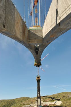
A view of the main arch’s double-legged section merging into its single-legged section where the two sides will meet.
Taking the nemesis out of the arch
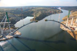
The arch has been constructed following a cantilever construction casting in situ each segment with a form traveler. In this process there was a cantilever from each side of the river that grew gradually and met each other at the crown of the arch. For the construction of a cantilever 629.9 ft long, a temporary cable-stay system was necessary. The temporary pylon of this system is formed by the main piers (pier 6 and 15) and the temporary towers located over the deck in the main piers.
The cables transfer the weight of the segments to the retaining foundations located in the adjacent piers to the main piers. In these foundations, a set of ground anchors were erected to transmit the loads to the rock.
The success in the execution of the bridge was based mainly on how to solve both cantilever structures with a most peculiar geometry. The depth and width of the section were variable along the cantilever, which enormously complicated the formwork installation, rebar placing and concrete pouring. That is the reason why the travelling formwork selection and concrete type selection were a key in the project success.
The supplier of the travelers was a Spanish company (Rubrica) and the detailed design was carried out by this company with the support of the FCC Technical Department.
The arch was built with high-performance (80 MPa/11.4 ksi), self-consolidating concrete. Whilst the consistency of this material was fluid enough to fill in all the voids between the rebar with no need for vibrating, it required formwork on all the sides of the cross-section. The travelers were consequently designed with forms that, once sealed, were water-tight to avert leakage.
In each cantilever, there were two travelers for the construction of the double section. Where the double section changed to a single section, the two travelers joined in only one traveler through a complex process.
The bridge was instrumented throughout construction to monitor a series of parameters, but most intensely during cantilever construction.
The data continuously recorded by the sensors were transmitted to a website where real-time and historic information could be visualized. In addition, each sensor was programmed to immediately send an alarm signal to the site supervisors’ cell phones when a given threshold value was exceeded.
This system ensured exhaustive control of bridge behavior, even when no work was underway.
Four types of sensors were used:
1. Geometric monitoring
a. Targets and prisms on the arch, piers and provisional towers: Sole data not automatically recorded, with manual readings taken at certain times during each construction cycle; and
b. Clinometer on piers and towers.
2. Environmental monitoring
a. Ambient temperature, humidity, wind;
b. Concrete temperature in arch, piers 6 and 15 and provisional piers; and
c. Temperature in stay cables.
3. Stress monitoring
a. Strain gauges on stay cables;
b. Strain gauges on arch reinforcing steel;
c. Strain gauges on provisional towers; and
d. Load cells on ground anchors.
4. Terrain movement monitoring
a. Strain gauges on arch foundations.
For geometric control, the actual position of the arch at each stage was compared to the theoretical position for the thermal conditions prevailing. With this system it was possible to make geometrical adjustments during construction.
One of the most challenging operations was the arch closure. The closure was performed in August 2015, one of the warmest and sunniest times of the year in the location of the bridge. In August, thermally induced daily movements were at their greatest.
These daily movements ranged as follows:
- Daily stay-cable heating was at its most intense. Thermal daily variations of up to 75ºF were recorded in the cables, generating downward movements of up to 0.4 ft; and
- Daily transverse solar radiation on the cantilever also was at its most intense, inducing horizontal movements of around 2.5 in. between 9 a.m. and 11 a.m.
A steel structure consisting of four longitudinal profiles positioned in the key segment near each corner of the cross section of the arch was designed to reduce these relative movements. It was received with high-strength, quick-setting mortar early in the morning before the effects of solar radiation appeared. After the mortar hardened, the connection was pre-stressed.
This structure was set in place on Aug. 4, 2015, and the closing segment was cast on Aug. 6. The operation was successful and the relative error between the two cantilevers at the key and the absolute error after that operation were both under 0.4 in.
After the arch closure, the cable-stayed system was removed and the piers over the arch were erected. The last step of the construction process was the construction of the deck over the arch. Like the approaches, the deck was constructed with two movable scaffoldings. In this case the two scaffoldings had to advance from north to south in a symmetrical way to avoid asymmetrical loads over the arch that could produce huge bending moments.
The closure of the deck at the crown took place in summer 2016.
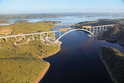
An aerial view of the entire span, prior to full deck completion.
Enduring the endeavor
Erecting an arch of this scale for a bridge in which the structural scheme during construction differs widely from its in-service functionality was a complex endeavor.
The extra detailing and designing required to address this complexity was performed by FCC’s Engineering Department, which also provided worksite support. The authors of the design verified all the work conducted in this stage of the project, ensuring full cooperation among all the agents involved.