N.J. Turnpike Interchange 14A Connector Bridge widening overcame significant challenges, to the benefit of a larger project
Interchange 14A, located along the Hudson County Extension, has earned its reputation as the New Jersey Turnpike Authority’s (NJTA) most problematic northern interchange. It had become notorious for congestion and causing adverse impacts to traveler mobility.
This interchange provides access to the Port Authority of New York & New Jersey’s Global Container Terminal Bayonne—the closest terminal to the harbor entrance for employees and commerce by two hours—and serves the communities of Bayonne and Jersey City. Substandard geometric features, poor access to and from N.J. Route 440, and a 56,000 ADT created a traffic bottleneck.
As a result, travel between the NJTA’s Hudson County Extension and the Bayonne-Jersey City waterfront port commerce district meant battling frequent traffic jams and delays. Predictions anticipated that land development projects, and an expansion of the Global Container Terminal, would increase interchange traffic 93% by 2035, further hindering mobility in and around the interchange.
As part of NJTA’s $300 million toll-funded Interchange 14A improvement project, Gannett Fleming provided environmental documentation, preliminary and final engineering design services, and construction management. Project objectives included handling future traffic volume by optimizing operational improvements as well as minimizing construction costs, property acquisitions, and impacts on the environment and the surrounding community.
The compact footprint of the interchange, combined with limited right-of-way, dense utilities, and the need to maintain vehicular and rail traffic during construction presented many challenges. The interchange improvements consisted of an intricate network of horizontally curved roadway (Figure 1) that required the design and construction of five new horizontally curved bridges, three bridge widenings, and numerous ancillary structures including retaining walls, noise barriers, sign support structures, and culverts.
Although site restrictions presented unique challenges to most of the structures, it was the replacement bridge carrying reconfigured Connector Roadways ET and TE that resulted in the most significant challenges. This complex bridge replacement represented a “project within a project” and required several innovations to achieve success.
EXISTING CONNECTOR BRIDGE
The existing bridge, built in 1955, carried Connector Roadways ET and TE over Route 440, the Lehigh Valley Railroad Company, the Central Railroad of New Jersey, and local roads. Measuring approximately 1,000 ft long, the original structure provided a connector between the Interchange 14A toll plaza and the local roadway network, including Port Jersey Boulevard.
At the northern end of the structure, Connector Roadways ET and TE each provided a single lane of traffic along separate, non-concentric curved alignments. Near the center of the structure, the two roadways came together at a gore. To the north of the gore, the geometry of the two curved roadways became concentric, then transitioned to a tangent, while providing a single traffic lane in each direction.
The existing bridge consisted of simple-span rolled steel stringers composite with a cast-in-place concrete deck. The substructure consisted of cast-in-place concrete stub abutments and a combination of hammerhead and multi-column piers, all supported on pile foundations.
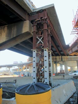
The team designed a counterweight system to provide structural stability for the pier during the temporary loading condition whereby live load was present only on one side of the hammerhead pier.
NEED FOR REPLACEMENT
The proposed geometric improvements to Interchange 14A included the realignment of Connector Roadways ET and TE. In addition, widening the new roadways was necessary to accommodate additional lanes. Although the new bridge would have a similar split/gore geometry as the existing bridge, the improved geometry and the need for a wider structure warranted its replacement.
A variety of factors came into play when developing structural alternatives for the replacement bridge. These factors included: span configuration and substructure location, roadway curvature, superstructure types and materials, support skew, future deck replacement requirements, depth of superstructure envelope, geotechnical parameters, utility locations, and constructability. In addition, inbound and outbound traffic continued throughout construction, so to minimize traffic disruption, construction of the replacement bridge commenced in stages.
The original intention of the connector bridge being located near the toll plaza was to accommodate three travel lanes with right shoulders in each direction. This would not only allow for greater traffic throughput when compared to the existing bridge but also accommodate toll plaza queuing on the bridge. However, a traffic study was prepared during final design that evaluated future traffic needs at the interchange assuming an all-electronic tolling (AET) configuration implementation at the toll plaza. Although this configuration would not start immediately upon the completion of the new interchange, NJTA’s plans for AET implementation allowed a significant reduction in the width of the proposed bridge. The new bridge would therefore only require two lanes of traffic with shoulders in each direction.
Due to the combined width of the two roadways and the need to separate them to the north of the gore, recommendations included independent deck slabs separated by a 1-in. open joint. This separation created simplified construction under staged conditions.
Since the project site is in a congested urbanized area, numerous physical features complicated the layout of the replacement bridge. In addition to the existing features that remained in service, the new bridge had to be compatible with several proposed new features that were part of the improvement project, including a new ramp roadway constructed below the new bridge on an abandoned rail siding and a proposed roundabout under the northernmost spans to provide access to the toll plaza for local traffic. The inclusion of the roundabout, combined with the use of a common full-height abutment at the south end of the bridge, resulted in a total bridge length measuring 1,000 ft and 1,073 ft for the Connector ET and TE bridges, respectively.
SUPERSTRUCTURE DESIGN
The numerous physical features present below the structure dictated span arrangements for the two connector bridges. Impacting the span configuration and substructure locations were:
- Lateral and vertical clearance requirements
- Sight distance requirements
- Span length limitations dictated by available structure depth
- Minimizing the overlapping footprint between the existing and proposed bridges to better accommodate staged construction
Considering these restraints, the pier and abutment locations resulted in a seven-span configuration for Connector ET and an eight-span configuration for Connector TE.
The new bridge, designed with welded steel plate I-girders, with webs varying in depth from 65 to 74 in., supports a concrete deck. The girders, fabricated with horizontal curvature, are now compatible with roadway alignment. Additionally, adding several radii transitions along the baseline resulted in radii ranging from 496 ft to 1,310 ft. The team selected steel plate girders, commonly fabricated for complicated horizontal curves, a cost-effective approach that can easily accommodate future widening. Since the span lengths and structure depths proposed for this structure were compatible with Grade 50W steel, the team did not consider higher strength steels. To minimize the number of deck joints required, the team designed the beams as multi-span continuous units and provided modular deck joints at the piers and abutments.
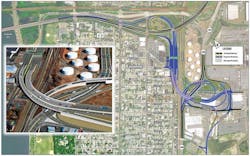
Figure 1. Diagram of Overall Interchange Improvements
SUBSTRUCTURE DESIGN
While laying out the substructure locations, the design team made efforts to minimize or eliminate substructural skews to mitigate adverse structural issues such as bearing uplift, increased torsional stresses in the beams, and less predictable girder displacements.
Due to the split alignment of the two roadways to the north of the gore, the proposed bridge required two separate abutments at the north end. Due to their low height, cast-in-place concrete cantilevered abutments founded on piles were the most cost-effective at these locations. Both abutment locations coincided with existing connector bridge foundations that consisted of pile groups, so the team removed several existing piles before the installation of the proposed foundation’s piles.
At the south end of the bridge, the height of the new abutment warranted the use of a two-component system consisting of a pile-supported, cast-in-place concrete stub abutment providing support to the bridge superstructure with a single row of H-piles and a mechanically stabilized earth retaining wall system designed to retain the embankment behind the abutment.
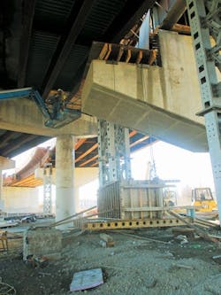
Most of the piers supporting the new structure included the design of single-column hammerhead piers, each supported on a single-drilled shaft foundation. However, the piers adjacent to the railway included the design of wall piers to meet American Railway Engineering and Maintenance-of-Way Association crash wall requirements. The cast-in-place concrete wall piers support multiple drilled shaft foundations. The use of drilled shafts in lieu of driven piles intended to minimize vibration-induced displacements that could have adversely impacted adjacent rail lines and underground utilities. This also minimized risk to the new structure during staged construction and helped reduce noise during construction.
At two pier locations, each end required a steel-box cross girder supported by a single column drilled shaft at each end. The need for outrigger-type straddle bents was necessary at these locations since there was inadequate space below the structure to provide a more conventional type of pier bent. The cross girder construction seamlessly integrated with the longitudinal beams, given the limited available structure envelope at these locations. One of the beams was located near the north end of the bridge and supported only Connector Roadway TE. The other cross girder was located near the southern end of the bridge and supported both roadways. This girder measured 116 ft in length and required bolted field splices, creating small pieces for shipment. Since Connectors ET and TE were in different stages of construction, the cross girder supporting both roadways sustained temporary loading conditions.
CONSTRUCTION CHALLENGES AND SUCCESS
Constructed by Union Paving and Construction Co. Inc. of Mountainside, New Jersey, this bridge represented the most challenging aspect of the interchange project. Although minimized, the footprint of the replacement structure overlapped portions of the existing bridge due to the restrictive site conditions. This created several complications for bridge demolition and construction because northbound and southbound traffic had to continue throughout construction.
The improved alignment of the connector roadway placed the southern half of the new bridge far enough away from the existing bridge to allow the two lanes of bidirectional traffic to remain on the southern portion of the existing bridge during Stage 1. However, to the north of the gore, the two split roadways overlapped the existing roadways. To maintain two lanes through the northern half of the structure, northbound and southbound lanes were rerouted across the existing Connector ET segment. This allowed the contractor to demolish and replace the Connector TE leg during the first stage of construction. The two lanes shifted onto the new bridge during Stage 2, taking advantage of the wider cross-section provided on the new Connector TE leg to accommodate both traffic lanes.
To make this scheme work, portions of the existing bridge needed widening near the gore area. The sliver widening required new temporary steel beams to support a cast-in-place concrete deck extension. In addition, several temporary hydraulic supports provided support for portions of the existing superstructure that had to remain in service during Stage 1.
Due to the proximity of the new structure to the existing supports at the gore area, construction stopped on one of the new hammerhead pier caps. The team had to delay the construction of a portion of the new pier cap until the demolition of the interfering components during Stage 2. The team designed a counterweight system to provide structural stability for the pier during the temporary loading condition whereby live load was present only on one side of the hammerhead pier. Once both traffic lanes shifted to the new TE roadway, the team demolished the existing ET bridge to allow for completion of the partially constructed pier cap.
The unique and innovative solutions incorporated into this $47 million structural replacement resulted in a wider bridge with an improved alignment that meets current structural and geometric standards, all while maintaining traffic movements above and below the structure during its construction. As a result, the bridge stands out as the showpiece feature of this successful interchange improvement project.