No disruption
The sustained focus on rebuilding our transportation infrastructure is accompanied by an objective that rivals controlling project costs: Keep the traffic in motion.
At Ramp C to the Brooklyn Bridge, an innovative temporary support system was engineered to enable replacement of failing concrete piers with two-piece steel piers, using precise and controlled operations beneath the existing superstructure. Five piers were replaced and there was no disruption to the flow of vehicles on the ramp above.
Head north on FDR Drive from Lower Manhattan and Ramp C will take you to the Brooklyn Bridge, Brooklyn bound. From behind the wheel, the perspective is just another single-lane connecting ramp, except that the skyline ahead is dominated by the historic and uniquely beautiful Brooklyn Bridge. After a gentle climb, the ramp curves to the west and crosses over FDR Drive, then sends you toward the bridge’s Manhattan anchorage. There is no way for the driver to know that below the ramp lies the East River Greenway, full of bikers and runners, its adjacent hardscaped park and where a team from Skanska USA removed the concrete piers on which the ramp used to sit.
The Ramp C superstructure is composed of multiple simple spans of approximately 80 ft to 100 ft in length, each with three parallel steel stringers typically spaced 7 ft 9 in. center to center. Prior to this project, the stringers were supported by common T-shaped concrete piers that sat on rectangular pile caps with H-piles below. The contract documents specified that five consecutive piers were to be replaced, and that all pile caps were to remain. This scope of work would have been fairly straightforward if the superstructure above had not been in the way.
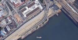
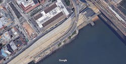
Aerial view of Ramp C to the Brooklyn Bridge as seen on Google Earth.
Getting it right
A number of challenges were presented regarding the design of the temporary support system considering the contract requirements and Skanska’s preferences:
- Design a universal temporary support system that accommodates variable geometry between five locations;
- Take advantage of the existing pile caps for support and do not introduce independent temporary foundations;
- Include rigging provisions for both demolition of the existing concrete piers and erection of the new steel piers;
- Provide a work-around at Bent 1 where the pier cap extends beyond the FDR Drive structure’s east fascia;
- Limit temporary structure, equipment and excavation to the existing curb line east of the piers;
- Incorporate hinge bases and stringer temporary bearings from a recent Skanska project (by others); and
- Coordinate new steel delivery beneath FDR Drive, off-loading and partial erection using a Demag AC40 hydraulic crane.
Challenge accepted, and it was clear that a unique 3-D puzzle was ours to build. The first task was to draft a general plan of the existing structure and to summarize key information at each pier including the pile cap length and width, the column base cross-section, and the stringer sizes and spacing with respect to the pier centerline. A site visit and a review of the elevation values stated in the contract drawings and the new pier shop drawings, combined with select survey shots of the existing structure, allowed us to draft accurate section views at each pier for both existing and new conditions. Using the contract documents and a CAD file for reference, preliminary calculations were performed to determine the required design loads and combinations. At this point most of the facts were in place so the design development process began.
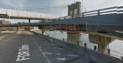
Google street view of the Brooklyn Bridge on FDR Drive.
Procedurally speaking
The proximity of the FDR Drive structure immediately west of Ramp C was a significant obstacle for both lateral and overhead clearance, so the decision was made to go east. On the east side there was a small but feasible window of opportunity for future crane positions, with boom clearance in mind. If the Ramp C east fascia is projected to ground level, the offset to the existing curb line is approximately 7 ft, which was enough to work with. Instead of diving into the temporary support design, visions of the most efficient and safe pier demolition and erection operations were formed. After many iterations and discussions with Skanska, ideal procedures were established and the structural design process could now begin with goals in sight. One key requirement of the procedures was the ability to fully access the piers from the east side, which required separate temporary supports north and south of each pier, with no connecting bracing. The smallest existing pile cap, at the lowest pier, controlled the layout of the temporary supports. Accounting for minimum edge distance at the outermost anchor rods, north/south temporary support spacing of 8 ft and east/west column spacing of 7 ft were the resulting dimensions.
Bent 1 was quickly identified as the controlling design of all five locations, considering the adjacent spans are of maximum length and the superstructure is at its highest point. In addition, the existing Bent 1 pier dimensions were greater than the other four. Allowances were made in the design loads to suspend large pieces of the piers from the temporary supports, consistent with the envisioned construction operations. Preliminary structural models of Bents 1 and 32E were created and cap beams were sized: W36 x 170 for the maximum forces at Bent 1 and W36 x 135 for the lower forces at Bents 29E-32E.
Thinking back to one of the previous bullet points, two more elements of the temporary support system were already in place and the load capacities were sufficient: the fixed temporary bearings at the top and the hinge bases at the bottom, working together to accommodate thermal movement of the superstructure. In order to re-support the existing stringers, lifting provisions were introduced beneath the hinge bases in the form of double-channel jacking assemblies that received 200-ton hydraulic cylinders, and finger shim plates during the lifting operation. The bottom flanges of the channels were set on a pair of grout pads and fastened to adhesive anchor rods in the existing pile caps; the hinge bases were bolted to the top flanges.
Pieces of the puzzle were taking shape and engineers went back to the CAD file to study the section views, specifically to identify the low stringer in each group of six (three north of the pier and three south). It was determined that a minimum ½-in. shim gap was adequate for constructability, and that the north and south cap beams should be at the same elevation, so the top of steel elevation for each cap beam pair was calculated as its low stringer bottom flange minus ½ in. Next up, the five remaining higher stringers were addressed. Depending on the roadway profile and superelevation, and the change in stringer depths, the range in stringer bottom flange elevations was approximately 13 in. and again Bent 1 controlled. Stringer-specific bolsters, which were slices of W36 x 135 with end plates and stiffeners, or welded shim stacks, were implemented and a minimum bolster height of 6 in. was established based on weld access for fabrication. Top to bottom, there were now temporary bearings, loose shims, bolsters or shim stacks, cap beams, a space reserved for columns and bracing, hinge bases, and jacking assemblies.
Again section views were studied, and a spreadsheet of required column dimensions for each of the five locations was created. One spreadsheet input was the height of a repetitive unit of two columns with end plates and cross-bracing between: the typical module. The height of the typical module was manipulated, then the resulting quantities per location, plus remaining height to fill, were studied and optimized. Engineers arrived at a clean dimension of 8 ft for the typical module height and five unique filler module heights were defined. Skanska’s plan was to replace two piers concurrently, in a leap-frog pattern, and the goal was to minimize temporary steel fabrication through reuse of components between locations. The module design elements were W14 x 90 columns, WT4 x 14 tension/compression cross-bracing, bolted end plates for shear connections, and bolted outside splice plates on both flanges to maintain column stiffness between modules. The temporary support structure was complete, and all that remained was how the piers were going to be swapped out.
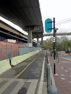
One challenge regarding the design of the temporary support system was limiting the temporary structure, equipment and excavation to the existing curb line east of the piers.
The need to move
As mentioned, allowances were made in the design loads for the construction operations, and the numbers could be tweaked if necessary, pending the results of the rigging equipment designs and the associated load paths. The clear dimension between north and south temporary support columns was 6 ft 10 in., and after the Bent 1 pier cap thickness of 3 ft 8 in. was removed, an available gap of 1 ft 7 in. remained at each side. It was understood that no matter which solutions we arrived at, unwieldy pieces of structure were going to have to be moved with very tight clearances. There was some flexibility in the existing pier demolition because the large mass of concrete could be cut into smaller pieces. There was no flexibility in the new pier erection, regarding sizes and weights, because the steel was already fabricated in two pieces: A column and a cap with a bolted field splice. The previously envisioned erection operation required the cap be hoisted first and the column rolled in beneath; a lifting frame and a runway system were needed to pull this off. The shape of the existing and new pier caps was very similar, so why not remove the existing pier cap using this same lifting frame?
Demolition was controlled, since the existing pier cap outweighed the entire new pier (49.1 kip vs 39.7 kip), and the resulting design was a pair of Grade 50 C15 x 50 channels spaced
4 ft back to back, with a pair of 8-in. extra-strong pipes as bearing members between. Bolted end plates on the pipes allowed assembly around the existing pier column, and lift lugs at the four corners served as 10-ton chain-hoist connection points. The lifting frame relied on W12 x 40 header beams between north and south temporary supports at the east and west ends of the cap beams. In order to accommodate differential rotation of north and south temporary supports during thermal movement of the superstructure, Teflon pads and slotted holes were incorporated in the header beam pipe bolster connections.
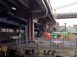
New pier replacements on Ramp C to the Brooklyn Bridge.
A difficult fitting
To recap, the design so far included temporary supports, a lifting frame with header beams and a runway system concept. The remaining pieces of the puzzle centered on removing the existing pier column. With the cap supported by the lifting frame, the first step in the pier demolition operation was to wire-saw just below the cap column interface, then lift the cap 2 in. to provide clearance for column demolition. Why not lift more than 2 in.? An unavoidable theme throughout the rigging design process was interferences. Lifting the cap higher required raising the header beams because the minimum headroom on the chain hoists was insufficient. Raising the header beams was not possible because they would contact the existing fascia stringers at certain locations. Lowering the lifting frame relative to the pier cap also was not possible because the lifting frame would conflict with the column demolition; the scenario for the new column roll-in was similar.
One might consider using the runway system to roll out the existing pier column to a position with improved access. This would have been an excellent solution if there were enough space between the temporary supports and the column. There was maybe an inch on each side.
The north-south dimension of the existing pier column was significantly larger than the new (6 ft at Bent 1 vs. 4 ft 3½ in.). Another window of opportunity was identified. After a careful study in plan, section and elevation views, a second pair of W12 x 40 header beams was inserted into the puzzle, again spanning between north and south temporary supports, and now directly over the W14 x 90 columns and between the existing stringers. The previous outside header beams would be dedicated to the pier cap, and the latest inside header beams would handle the column demolition.
Again, positioning was critical because too high interfered with certain end diaphragms and too low interfered with the new pier cap erection. The plan was to hang a pair of W12 x 35 trolley beams from the inside header beams that would facilitate an out and down column demolition, block by block. There was just enough room for the required 6-ton trolleys and chain hoists to straddle the cap-lifting frame and clear the temporary supports.
Two rigging designs were developed for the column block demolition: One for the trapped top block (10.1 kip maximum) and
a faster system for the remaining blocks (21.6 kip maximum) down to the pile cap.
Once the bottom column block was removed, the next step was simply to lower the pier cap to the ground and cut it into manageable pieces. There were two sources of conflict at Bent 1 to resolve. First, remember the work-around challenge of the pier cap over FDR Drive? A low-impact modification was made that involved cutting 2 ft off the west end of the pier cap by means of a telehandler positioned in the east shoulder of FDR Drive. The shortened pier cap, and a modestly reconfigured lifting frame, would now clear the FDR Drive structure and both could be lowered to the ground. Second, the stringers at Bent 1 are skewed to the pier centerline due to the horizontal curve of the roadway, and there is maximum superelevation. The temporary bearings had to match the stringer alignments, and this resulted in the need for custom stringer bolsters and interferences with the trolley operation. Hangers were added between the inside header beams and the trolley beams to allow the trolleys to pass below the temporary bearings. The matching superelevation was built into the new pier cap, which required taller pipe bolsters for the inside header beams to provide an inch or so of clearance.
At this point a bolt together kit of temporary steel was established. One outstanding accessory was the previously revealed runway system, and again the design proved to be a patiently choreographed process. For each pier, there was an available clear height between the top of the existing pile cap, and the bottom of the pier cap and its lifting frame; the new pier cap was already suspended above according to the erection procedure. Each new pier column was placed in the CAD file to best split the top and bottom clearances, which were generously 1 in. each. From this study, a consistent dimension was chosen for the nominal roll-in clearance between the column’s base plate and the existing pile cap: 1¾ in. This dimension would accommodate ¾-in.-thick shelf angles as the base plate supports, and allow for deflection of the runway beams.
From here the structure took shape as a pair of W18 x 50 runway beams, spaced 5 ft 4 in., with C6 x 8.2 channel tracks for Hilman rollers. Cross beams connected the runway beams at both ends, and the framing was supported by bolsters on a temporary footing at the east end and the jacking assemblies at the west end. There was just enough real estate for the runway system to butt up to the existing east curb line and still provide a suitable footprint to trip-up and land the pier column within the 7-ft window previously described.
A question remained: How will crews connect five different pier columns to the runway beams? The most feasible means of supporting the columns was at the base plate, so a base plate study in CAD was the starting point and a few trends were identified. First, the north-south dimension of all base plate was constant at 4 ft 3½ in. and the east-west dimensions varied from 5 ft 2¼ in. at Bent 29E to 5 ft 10 5⁄8 in. at Bent 1. Second, all base plates contained the same size, quantity and general layout of anchor rod holes. Again, the north-south dimensions were constant, and there were four sets of east-west dimensions because the hole layout at Bents 31E and 32E was identical. The solution was to fabricate sets of interchangeable pipe hangers, with shelf angle ends, that were bolted to W8 x 24 hanger beams. The hanger beam top flanges received slotted holes that were compatible with Bents 29E and 30E, and the bottom flanges accommodated Bents 31E, 32E and 1. The intent was to flip the hanger beams when required to suit each location. Another pair of W8 x 24 beams, transverse now, provided support for the hanger beams and had the Hilman rollers welded at both ends. The runway frame was complete and it nested neatly between the runway beams, allowing the new pier columns to float over the existing pile caps.
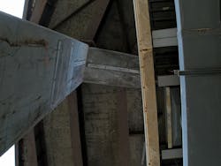
The pier cap at Bent 1 extends beyond the FDR Drive structure’s east fascia.
Planning the build
The Bent 1 demolition phase of the FDR Drive work-around had been solved and the erection phase was to be determined. We could not shorten the new pier cap, similar to the demolition operation, so the only option was to hoist the cap eccentric to the pier centerline. Fortunately, the trolley beams did the trick. A pair of underslung beams with four lift lugs and the 6-ton chain hoists would handle the lifting frame and pier cap until it was above the FDR Drive barrier. Then the assembly would be rolled west to the pier centerline. Once in position, slightly above its final elevation, the east pick points would have to be transferred to the lifting frame and the respective outside header beam to provide clearance for the column roll-in. The west pick points remained on the trolley beams, and we needed yet another special provision to wrap up the construction at Bent 1.
At Bents 29E-32E, the new pier erection was planned to conclude without additional equipment. The steps included: Lower the pier cap to barely contact the column, complete the bolted splice, hoist the entire assembly to free the column from the runway system; then land the column base plate on a 2-in.-thick shim, install the anchor rods and pour the grout pad. The trolley beams did not have sufficient strength to lift the spliced Bent 1 pier cap and column, and it was not practical to upgrade the members and connections due to clearance-related dimensional restrictions.
Plan B was to jack the runway. A pair of 10-ton hydraulic cylinders was inserted at the west end of the runway system to facilitate lifting the column and setting it on the shim plate. Then the anchor rods would be installed and the pier cap would be set and spliced. Skanska also could jack the runway at the other locations if desired, and this was stated as an option in the final procedure.
After many hours of detailed thinking, the puzzle was complete. Skanska’s Demag AC40 crane was now in the spotlight. Delivery vehicle positions and crane positions specific to the new pier cap and column off-loading were investigated, and the best fit was determined for each location. The tight clearances theme remained, and the goal was to provide a path on the hook for each piece from its delivery trailer to a staging position for future access. A variety of strategies were deployed and boom tip clearance in all directions was constantly examined; there was not the luxury of a foot or two. Producing overhead rigging designs for erecting the temporary supports was a walk in the park after the intense engineering to date.
Bent 1 was up first. The long lead-up to construction day one paid off, because the pier replacement was a success. The judiciously written procedures were followed and there were no required deviations. A field change was introduced regarding the four remaining piers: The existing pile caps were to be replaced. The temporary support system relied on the existing pile caps, so the necessary course of action was to design temporary foundations. Revised locations for the temporary supports were determined based on the varied north-south dimensions of the existing/new pile caps, then the corresponding stringer bottom flange elevations were surveyed. The survey values, influenced by the Ramp C profile and superelevation, sent the engineers back to the CAD file. By manipulating the temporary foundation elevations, combined with shuffling the temporary support filler modules, shim stacks and bolsters, minimal new fabrication was required. The bulk of the new temporary steel components was outside and inside header beams due to the increased spans, and sets were designed and detailed to be shared between two locations each using multiple bolt hole patterns, and in some cases slotted holes.
Location-specific support of excavation systems were designed and constructed between each pair of temporary foundations, and once the temporary supports were erected, Skanska was back in business.
The challenges presented by the Ramp C pier replacements forced the contractor-engineer team to think outside of the box. Undesirable site conditions, limited existing structure dimensions and engineering requirements intertwined to question the feasibility of certain aspects of the construction operations. The success of the project is attributed to a strong collaborative effort, extensive careful planning and creativity in the midst of a numbers-driven process.