Flat solution to a curved problem
While “blast and paint” rolls off the tongue easily, providing access to the underside of the Elysian Viaduct Bridge for rehabilitation work is anything but easy.
In fact, as the original bridge construction project neared completion, the September-October 1961 issue of the Official Journal of the California Highways and Public Works noted the “unusual structural solutions to several unique problems created by the difficult site.”
The Elysian Viaduct is a nearly half-mile-long steel girder and reinforced concrete box girder bridge on multi-column and single-column bents and pile foundations. Just north of downtown Los Angeles, the Elysian Viaduct sweeps northwest in a wide arc so that I-5 traffic can cross the Los Angeles River—and numerous other obstacles. Over a distance of 1,987 ft, spans 6 through 21 of the bridge cross the southbound entrance to I-5 from I-110; the Arroyo Secco spillway; I-110; North Figueroa St.; the south side of a Home Depot parking lot/north side of Cypress Park; North San Fernando Road; the Southern Pacific Railroad yard; the Los Angeles River; the Los Angeles River Greenway Trail; and Riverside Drive.
With such complicated logistics, typical access solutions would not yield optimum results. Traditional scaffold on trusses hung with tubes and clamps would have increased access costs, while flexible decking supported by cables would have slowed worker productivity and increased costs. For this project, the general contractor who submitted the winning bid proposed the use of a multi-point suspended access system, a solution just now gaining popularity.
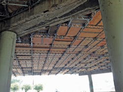
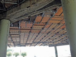
The suspended system allows a platform to be built in the air in modular segments. The first segment is hoisted into place and suspended from the girders using clamps and chains. From that base, additional modules are built outward using swing-out trusses placed by hand, pivoted and then locked in place. Plywood floor panels were placed on the trusses to create a flat, rigid and stable work surface. Because the deck has enough cantilever strength to support workers as they install new supporting chains for the next segment, workers were able to “leap frog” the deck as the job progressed, as well as extend the platform beyond the outside of the girders.
Prior to implementation, the California Department of Transportation (Caltrans) requested that a third-party engineering firm verify the structural integrity of the platform design; moreover, a field inspection of components and refurbishment of the chain mid-project was to be performed. Because this project did not require heavy loads on the platform (most of the blast and paint equipment remained on the ground), platforms with a capacity of 25 lb per sq ft were specified; 50- and 75-lb/sq-ft ratings also were available, and all platforms had a 4:1 safety margin. Considering an 8-ft × 8-ft platform has 64 sq ft of area, a 25-lb/sq-ft platform could safely support loads up to 1,600 lb—far more than required for blast and paint work.
Because the girders come off the pier at unique angles, engineers had to design hundreds of special joists so that the platform would firmly abut the piers.
Project scope
In November 2014, Caltrans approved $19.4 million in funding for rehabilitation of the Elysian Viaduct by removing rust, cleaning and painting to maintain the bridge load capacity.
Bidding was opened on April 1, 2015, and the winning bid of $16.6 million was submitted by general contractor CL Industrial Coatings Inc. (CLIC) of Stanton, Calif., which subcontracted the Los Angeles branch of the Safway Group for access and environmental containment.
The project began in October 2015 with a 765 working-day schedule.
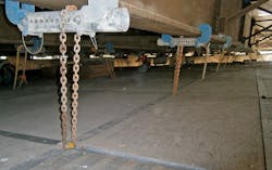
These girder clamps connect to the bridge to provide suspension points for the platform chain. This section of the platform has been shrink-wrapped and already blasted.
Planning for success
The Elysian Viaduct’s curved steel girders were the first of their kind in California. Instead of right angles, the girders come off every pier at unique angles. As a result, standard square or rectangular work platforms would not abut the piers.
Thus, the first phase of the project required application and design engineers to analyze every pier and calculate the correct size for the “pie-shaped” platform segments necessary to transition to the standard 8-ft x 8-ft platform sizes. After design, the fabrication team produced the hundreds of pieces required to complete work on the initial stages of this giant jigsaw puzzle. Recognizing a need, engineers also began designing a telescoping bracket to connect more standard platform sections to the piers and minimize the need for additional parts.
While the planning for the multi-point suspended platforms had its complications, design and erection proceeded at a pace faster than hanging traditional scaffold, which often requires a greater number of components. After the first standard platforms were hoisted, the crew of eight (five in the air, three on the ground feeding components) could move efficiently, erecting an average of 1,500 sq ft of platform in an eight-hour shift.
In all, 45,000 sq ft of suspended platform were employed for the project, which covered a work area of more than 234,000 sq ft. The platform was divided so that work could proceed in three sections: one for sandblasting and prepping, a second for priming and a third for finish coating. After the blasting and prepping in one area was completed, the platform was dismantled and moved to the next area. This approach minimized rental costs and increased operational efficiency for both the erection and blast and paint crews.
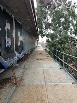
The design of the multi-point suspended platform allowed it to extend up to 8 ft beyond the suspension point, in this case for easy access to the outside of the girder. Note the toe boards, an added measure against dropped objects.
Blast-off
Spot blasting to remove rust and graffiti was done in accordance with Society for Protective Coatings specification SP 6 “Commercial Blast Cleaning.” SP 6 states that, “A commercial blast-cleaned surface, when viewed without magnification, shall be free of all visible oil, grease, dust, dirt, mill scale, rust, coating, oxides, corrosion products and other foreign matter, except for staining as noted.”
For this project, crews used garnet as the blasting media. Because the Elysian Viaduct was a lead abatement project, all the used blast media was vacuumed and removed from the site by a licensed hazardous waste hauler. To contain the media and blasting byproducts, workers created an environmental control barrier using 12-ml PVC shrink-wrap. Where bonding was not feasible, the shrink-wrap was glued or taped in order to create better control compared to tarping, a critical consideration given the two waterways.
After spot blasting, workers followed Caltrans’ pre-mixed waterborne (PWB) specification, which for the Viaduct started with a prime coat (PWB 145E, red primer paint). After the prime coat, the entire painted area received a 5,000-psi pressure wash. After drying, the Viaduct received an undercoat (PWB 146E, pink primer paint) as well as a striped coat with PWB 146E. The striped-coat technique required additional paint on the edges of the steel; thin areas were otherwise prone to failure without the extra effort to build up a coat of sufficient thickness. Finally, a first finish coat (PWB 161A, non-leafing aluminum finish paint, waterborne acrylic latex vehicle) and a second and final finish coat (PWB 162A, leafing aluminum finish paint, waterborne acrylic latex vehicle) were applied.
On span 8, Caltrans specified a minimum vertical clearance of 14 ft 3 in. for vehicular traffic . . . and the bottom of the Viaduct was 16 ft above the road. The blast and paint contractor indicated that it could complete work if provided with 18 in. of room. With 2 in. to spare, the access contractor designed and fabricated a new suspension method to connect that solved the problem. With a vertical clearance of 14 ft 5 in. for the work platform, traffic could proceed without lane closures.
The blast and paint crew noted that the large, flat deck of the suspended modular platform offered several improvements over traditional hung scaffolding. The flat deck improved mobility because it was more rigid than other options and because there were far fewer items blocking the travel path—just a chain every 8-16 ft—which might have created tripping hazards. This made moving blast, paint and vacuum hoses much easier, and it simplified collection of used blast media. In short, workers were safer and more productive.


