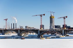
Tower cranes become unlikely heroes of downtown Minneapolis’ Third Avenue bridge project
The Third Avenue bridge connecting downtown Minneapolis to the city’s northeast side needed rehabilitation. Everyone agreed on that—but the bridge was not going to make it easy.
Diverse factors about its location, shape, original construction materials, and even historical significance made for a challenging project. It took a half-dozen stakeholders coming together to make it possible: the Minnesota Department of Transportation (MnDOT); engineering consultant, HNTB; the project’s general contractor, Ames Construction; Ames’ engineering subcontractor, Finley Engineering Group; crane suppliers Dawes Rigging & Crane Rental and ALL Tower Crane; and finally, the Minnesota State Historic Preservation Office (SHPO).
The Third Avenue bridge opened more than a century ago, on June 14, 1918. Its famous S-curve shape was dictated by difficult foundation conditions created by its proximity just upstream from St. Anthony Falls spillway—proving that the structure has been obstinate since birth. Its concrete arches surround a steel skeleton called a Milan arch, an early hallmark of bridge building that has since given way to rebar-reinforced concrete. “It’s a construction technique that is very symbolic of that era,” said Jerry Volz, vice president of bridges and structures for Ames Construction.
An additional difficulty was that the bridge features several historic traits, right down to the railing, a decorative element that was nonetheless deemed historic. And not only is the bridge historic, so are nearby cobblestone streets and adjacent parkland, which presented site access problems, particularly for the multitude of big trucks that would be necessary to haul traditional cranes to the site or even build an access bridge from which to work.
What always works wouldn’t work
Bridge rehab work is, of course, often performed with a crane barge, but that was not feasible here, either. Due to the structure’s S-curve and its location near the spillway, the structure is not accessible by barge. Nor was using standard all-terrain or crawler cranes an option, due to concerns about load bearing and stress on the spring line. Cranes could only be positioned on certain parts of the bridge—and then only in specific orientations, limiting their effectiveness.
Seeking alternative options, the Ames and Finley teams turned their attention to tower cranes. Employing tower cranes was an attractive idea, because they would not add any load to the bridge deck. Since the bridge sat on large box columns, engineers considered the possibility that the tower cranes could be mounted within these columns. They were concerned about possible limitations of the towers’ capacity and reach, so they explored the idea further. In so doing, work began with Dawes Rigging & Crane Rental Inc. and their rep Ryan Harrison, who was the catalyst for all lift services at the site; as towers began to evolve as a primary solution to this challenging application, he connected the team to ALL’s dedicated tower crane division.
Inspiration strikes
Typical tower attachments were too large for the space available. The Finley team keyed in on a unique solution—to use the existing bridge piers as the anchors, the idea being to take a section of tower, imbed it in the box column, reinforce it with concrete, then bolt on the rest of the tower crane as normal. In other words, literally drop the towers into the piers.
Exploring the possibility would take close collaboration between all the involved parties. “We never tried this idea before. Pulling it off became very interactive between us, Ames, and ALL,” said Craig Finley, principal engineer for Finley Engineering Group.
Each entity was responsible for certain aspects of the planning. Finley’s engineers conceptualized potential solutions. The engineers at ALL Tower Crane contributed crane reactions and ensured the loads dictated by the concepts were feasible. The Ames team assisted with perspective from on-the-ground execution, particularly related to embedding the tower anchors.
Finley employed SOFiSTiK structural engineering and Autodesk Bridge Information Modeling (BrIM) software to plan the job, and much of the experimentation surrounding the bridge-as-anchor idea happened within this 3-D virtual world. “MnDOT had accurate dimensions that we were able to use to create our virtual environment,” said Finley. “By tying everything to the analysis model, we sequenced the visualization animations and developed every step of construction. There were still little anomalies of perspective that cropped up. There might be a space on the model that appeared rectangular, but in the real world was more trapezoidal. So, we’d come up with a Plan B.”
A lot of effort went into investigating how to mount the tower bases inside the existing pier column without damaging the existing bridge—at the same time meeting the tight load and geometric tolerances. “When picking, cranes have a slight deflection,” said Volz. “But we didn’t have a lot of room for deflection within the column. Finley’s work made sure we met MnDOT’s requirement of no impact to the existing pier walls.”
The engineers at ALL Tower Crane provided critical calculations for the capacities of the cranes and signed off on the loads the Finley team wanted to achieve. “We provided reactions from the crane, max allowable movements, and drawings for crane anchor stools,” said Sam Moyer, general manager of ALL Tower Crane. “Our main point of coordination with the Finley team was the interface where the equipment leaves the grillage and becomes the crane.”
Craig Finley said the work of ALL’s engineering team helped them answer this crucial question: How can we reinforce the column walls in a way that would not cause undue stress on the towers or the pier walls? “We used the existing piers to be the form for this interior plug. It transferred axial load through friction on the side of the piers, but also through the concrete we poured and the tie-downs in there,” said Finley. “That’s how the combination of loads and deflections were handled.”
A bridge reborn
When it came time to execute the plan, the Ames crew removed the bridge deck and opened the hollow portion of the columns down to the footings. This open portion was blasted to help ensure a clean surface. A tower section was fed into the base down to the bottom, rebar was inserted, then concrete was poured in. After the concrete had cured, the tower was erected. When the time comes in the project timeline to disassemble the tower cranes, a portion of it will remain inside the bridge, unseen. Crews will bring down the tower to the point where it can unbolt from the connection at pier level. Then they will pour a seal cap to cover the steel.
Three tower cranes went up on the bridge in January, with a fourth scheduled to be added in August. Tower erection was handled by Dawes Rigging & Crane Rental. Piers two and three each support Potain MDT 368 tower cranes (the fourth crane, slated to be erected in Pier 4, will also be this model), while pier 5 has a Potain MDT 389. The 389, an updated version of the 368, was chosen for pier 5 due to its improved onboard work-site zoning system for working around overhead obstructions. Hook heights range from 72 ft to 120 ft. The taller heights normally associated with tower cranes are not needed in this case, since the bridge is a horizontal rather than vertical structure. “I can’t say enough about Harrison and the Dawes team that assembled these units,” said Volz. “And they did it in the midst of a Minneapolis winter. Their efficiency was impressive. Within days, the cranes were erected and operational.”
From their strategic and well-anchored positions, the tower cranes are able to move a variety of construction materials across the bridge deck, where small rough-terrain cranes—light enough not to damage the deck—await to carry material throughout the project.
Wide-ranging work includes replacing the bridge deck; installing updated lighting, spandrels and pilasters; repairing the piers and historic ornamental railing; and creating 13-ft multiuse paths on both sides for pedestrians and bicyclists, with delineated lanes for each and separation from vehicle traffic. The tower cranes will act as material handlers for the bulk of these tasks, their horizontal booms and sliding trolleys providing uninterrupted, edge-to-edge access to all zones across the bridge. The construction project is slated to last until November 2022, with the work expected to extend the bridge’s service life another 50 years.
Based on the success of this project thus far, Volz is of the opinion tower cranes could end up being a secret weapon for bridge-restoration projects: “This project surely opened our eyes to the fact that tower cranes can be even more advantageous than barge-mounted cranes. It’s something we’ll definitely look at for future projects.”
This view is shared as well by Finley. “This was a first for us, and I’ve been doing this for more than 35 years,” he said. “But we quickly learned to love the towers’ ability to work 180 degrees and out to the midpoint of the span. All of a sudden, it changed the way we looked at towers. In the future, we’ll bring this idea to the table on the first go-round. It’s a good idea that works even better than we could have imagined.”


