Bridge and viaduct construction for a new transit corridor in San Diego
The Mid-Coast Corridor Transit Project (MCCTP) is the largest transit infrastructure project currently under construction in San Diego, California.
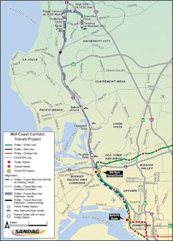
The project will provide an 11-mile light-rail transit (LRT) link between downtown San Diego and the University Town Center (UTC) business and education center, including the University of California San Diego (UCSD) campus. The $2.2 billion project includes 12 bridge and viaduct LRT structures, five aerial transit station structures, several unique wall structures, and geo-structural improvement below the track. The transit extension will use existing trolley tracks for the southernmost 3.5 miles and include construction of 11 miles of new double track that extends over the San Diego River. When complete, the LRT line will offer a continual ride from the international border, through downtown San Diego, to the University City. The project is being constructed using a Construction Manager/General Contractor approach (CM/GC). Construction began in 2016.
DELIVERY APPROACH
The 351-mile Los Angeles–San Diego–San Luis Obispo (LOSSAN) rail corridor is a critical freight link to the Port of San Diego and is the second-busiest intercity rail corridor in the U.S., supporting commuter, intercity, and freight rail services. Two major improvements to the LOSSAN corridor needed to be delivered in parallel with the Mid-Coast LRT project. The Elvira-to-Morena Double Track (EMDT) will add 2.6 miles of second main track along the railroad corridor between Balboa Avenue and S.R. 52 in San Diego. The San Diego River Bridge Double Track (SDRBDT) will add one mile of second main track and a complex structure across the San Diego River. Construction of the MCCTP prior to the LOSSAN improvements would preclude staged construction that maintains rail traffic in the busy corridor. Both the EMDT and SDRBDT projects needed to be built prior to the MCCTP construction, particularly for the bridges. Therefore, the projects were delivered under a single CM/GC approach by the San Diego Association of Governments (SANDAG) with several major stakeholders involved. Three independent but overlapping design teams were managed by SANDAG to complete the design effort. Extensive coordination was required between the design teams for physical and schedule compatibility.
For the CM/GC approach, the potential construction contractor team served during the design phase to provide construction input. A primary goal of the contractor was to help ensure effective use of space and resources, project compatibility, and schedule certainty for phased construction within the corridor. The team was also tasked to provide input on constructability. The Guaranteed Maximum Price (GMP) process was employed where the construction manager was awarded the construction contract.

STRUCTURES
Several types of structures are being constructed as part of the MCCTP including cast-in-place (CIP) and precast LRT bridges and viaducts, pedestrian bridges, retaining walls, and elevated stations. These structures were planned and designed to overcome site challenges, including seismically induced liquefaction, lateral spreading, fault rupture, river floodplains, a busy rail corridor, major freeway crossings, and a congested urban environment.
The MCCTP consists of 12 bridges including three viaducts with an approximate total length of 4 miles and a variety of retaining structures with a total length of 5 miles. The southern end of the new alignment extends north across several creeks with high potential for seismically induced soil movements and significant scour. As the corridor extends to the north outside the railroad right-of-way, at that point it extends into three major viaducts: the Nobel Viaduct, UCSD Viaduct, and Genesee Viaduct. Cast-in-place post-tensioned (CIP P/T) construction was selected as the preferred superstructure for the Nobel and UCSD viaducts as the most cost-effective and constructible option for their long spans. A combination of precast post-tensioned and CIP P/T superstructure was selected for the Genesee viaduct due to the congested urban environment and local streets. The CIP portions were more cost-effective, and the precast components had reduced impacts to the surrounding community.
CALIFORNIA’S FIRST CURVED SPLICED PRECAST U-GIRDER LRT BRIDGE
The proposed 1-mile-long Genesee Viaduct is located within the middle of a congested local urban arterial that is critical for accessing UCSD, dense residential housing, the UTC business center, local schools, and area shopping. Maintaining local traffic and minimizing impacts to the surrounding community were critical for this viaduct, and the primary driver of structure type and construction methods.
The Genesee Viaduct carries two parallel LRT tracks spaced at 14 ft 9 in. between the centerline of the tracks. The elevated structure supports two side-platform stations named as Executive Drive and UTC stations. The viaduct is currently under construction with an expected completion date of December 2021.
One of the requirements of the project during the design phase was to keep major intersections on Genesee Avenue open and operational during various stages of construction. Full closure of the intersections was only considered for nighttime occurring at one intersection at a time. Six locations were identified where precast girder spans were crossing over live traffic where this criterion applied.
In these locations, the design team developed an innovative approach to splice the precast girders at a staging area near the site, then transport the spliced segment to the site at night for erection. The spliced segment was to be erected and placed on shoring towers during a one-night closure of intersection. The length of the spliced segments varied from 140 ft to 180 ft.
FRAME TYPES
Precast U-girder construction was selected for the majority of the viaduct to minimize impacts from falsework. The viaduct is divided into 12 frames separated by expansion joints and in-span hinges. The span lengths vary from 140 ft to 225 ft.
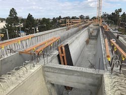
All precast girders are fabricated off-site and transported to the construction site. Once on site, the girders are spliced together by forming a CIP closure pour between girder ends and prestressing the girder segments for continuity under the final loading condition.
One of the challenges of using precast U-girders for construction is hauling and transportation of girders. Through designer and CM/GC collaboration, the precast girder layout was designed to limit girder lengths and the hauling weight of each unit below 100 tons. This was to reduce hauling cost and prevent the need for self-propelled modular transporters (SPMTs) for transportation between the casting yard and construction site. Spans were therefore each divided in two to four units of precast girders.
The viaduct is made up of three frame types with varied construction methods, girder assembly, and splicing operation.
Type 1: Precast girder frames: There are nine precast girder frames in the viaduct, consisting of precast U-girders spliced by one-stage or two-stage prestressing. For the five frames with traffic underneath, the first stage of prestressing is performed in two steps. Step 1 involves splicing girders for spans over the intersections in a staging area near the site and away from the traffic. After this splice operation is complete, the entire spliced segment is lifted and placed on temporary shoring towers on either side of the intersection. In step 2, a second prestressing tendon is used to splice the remaining girders that are not crossing any traffic while supported on shoring towers. Once all individual girders are spliced within each segment, a second stage of prestressing is performed to connect all the spliced segments in the frame together and form continuity between expansion joints. The remaining four frames, not crossing traffic, are spliced and prestressed in one stage.
Type 2: Precast CIP Hybrid frames: The longest span in the viaduct is a 225-ft crossing over La Jolla Village Drive. Due to weight, this span was too long to be spliced entirely at a staging area and lifted on temporary shoring towers in one piece. Therefore, an all-precast girder frame construction was not feasible at this location. Instead, the team proposed a hybrid precast/cast-in-place superstructure to reduce the spliced length over the intersection and still make use of precast girder construction in the adjacent spans of the frame.
Short CIP cantilevered spans were built on both sides of the intersection integral with the columns in the shape of a hammerhead outside of the required traffic opening at the intersection. The CIP segments are connected to precast girder segments by prestressing and through CIP closure pours.
In the same manner as the precast girder frames, the first stage of prestressing is performed in two steps. Step 1 involves splicing girders between the two CIP segments at a staging area near the site and away from traffic. After this splice operation is complete, the entire spliced segment is lifted and placed on temporary shoring towers on either side of the intersection. Step 2 is identical to that described for the precast girder frames.
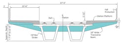
Type 3: CIP Station frames: The viaduct serves two aerial side-platform stations, each within a single structural frame. The side platforms are supported by a series of evenly spaced transverse beams connected to superstructure girders. Due to the complexity of aerial station construction and the presence of multiple transverse beams that require integral connections to the superstructure, it was decided to use a CIP box girder construction for the entirety of frames carrying aerial stations. Single-stage post-tensioning is performed at all CIP station frames.
SUPERSTRUCTURE/SUBSTRUCTURE
Three superstructure types were utilized throughout the viaduct to address the design needs for different types of loadings and frame construction.
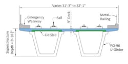
The cross-section at precast girder frames consists of two PCI 96-in.-deep U-girders connected with a 9-in.-thick CIP deck. The precast U-girder has 10-in.-thick webs and a 9-in.-thick bottom flange. The typical precast girder depth is 8 ft 10.5 in., including a minimum haunch thickness of 1 in. between the precast girder and the deck. Superstructure depth is constant in all precast girder frames. Straight girders are pre-tensioned at the fabrication yard, whereas curved girders are post-tensioned for resisting self-weight and construction loads up to the splice stage. A lid slab is incorporated in the cross-section of curved precast girders to improve the torsional resistance of the cross-section, particularly for the under-the-wet-deck pour.
The cross-section of CIP hammerhead cantilever superstructure in the hybrid frame closely matches the typical section at precast girder frames. At CIP cantilevers, the web thickness is increased to enhance the shear resistance of girders. The superstructure depth varies from 8 ft, 10.5 in. at the girder splice point to 11 ft at the face of column.
At aerial station frames, the typical section consists of a CIP box girder as the primary system. Attached to the box girder are station side platforms and transverse beam supports. The box girder consists of four webs. Typical web thickness is 12 in. The deck thickness is 9 in., similar to other cross-sections in the viaduct.
The two aerial station frames in the viaduct provide support for the station side platforms, as well as pedestrian bridges connecting the side platforms from the adjacent structures such as multilevel parking structures and elevator towers. At locations where a pedestrian bridge connects to the station frame, a cantilevered transverse beam is provided to support the pedestrian bridge superstructure. Pedestrian bridge supports are 12 ft wide and are rigidly connected to station frame superstructure.
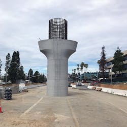
The viaduct substructure consists of single columns supported on single cast-in-drilled-hole (CIDH) piles. Column-to-superstructure connections at precast girder frames are either expansion joints or pins. A shallow 4-ft-deep cap beam is provided at the top of the column to provide a seat for precast girder spans and end diaphragms. Cap beams are post-tensioned using straight threaded bars. At the hybrid frame and the CIP station frames, columns are integrally connected to the superstructure to reduce negative moment demands near the bent and to better control seismic displacements of columns. Columns are circular with diameters that range 7-9 ft.
As the largest transit and transportation effort currently under construction in San Diego, the Mid-Coast Corridor Transit Project is recognized as the most important transportation improvement project in the city for expanding the transportation capacity and accommodating the future growing travel demands in the region.
The Genesee Viaduct, constructed within the median of a major arterial road, is the first curved spliced precast U-girder LRT bridge in Southern California. Several key decisions were made through a collaborative process by the design team and CM/GC resulting in innovative design techniques, improved design quality, and optimized construction cost and schedule.