NO. 2: Green Street Pedestrian Bridge
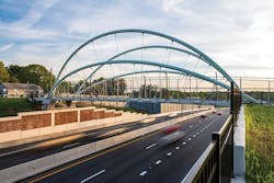
The Green Street Pedestrian Bridge is a unique, multi-ribbed, unbraced tied-arch structure spanning the newly reconstructed Salem Parkway.
Located in downtown Winston-Salem, North Carolina, the bridge connects the West Salem neighborhood with the city’s multiuse path, the nearby baseball stadium, and new developments planned for the area. The arching structure serves as an artful, iconic gateway into downtown, to inspire economic development and symbolize Winston-Salem’s 21st century aspirations.
The HDR team collaborated with project stakeholders to meet expectations on the bridge’s unique features including geometric layout, arch shape, hanger rod arrangement, and connection details.
A 32-ft-tall pair of inner arches incline outward at 13° and carry most of the bridge’s deadload. A lower pair of outer arches, inclined at 30°, reach 16 ft in height, and carry a smaller portion of the structure’s load. Each arch rib required a strategic design approach and a multi-phased staged structural analysis.
Cambered 6 in. at mid-span, the gently-curving bridge deck is supported by radially aligned, stainless-steel hanger rods—nine hanger rods to each arch rib, 36 hanger rods in total. For each arch, the hanger rod group plane is offset from the centerline rib plane, providing a constant deck cross section and avoiding outriggers. This improved the structural stability of the unbraced arch ribs by providing a restoring force against the outward torsional tendency of the ribs’ self-weight.
- The bridge has several complex geometric features that affected the design and continued through to fabrication and construction:
- Overall Configuration: Balancing unbraced arches that tilt from one side of the bridge to the other
- Arch ribs: Curvature and symmetry along the bridge span, interaction and proximity of end anchorages
- Upper Gussets: Location and orientation providing connectivity between differing arch rib planes and deck-level connection planes
- Lower Gusset Plates: Spatial alignment and orientation along the cambered concrete deck edge beams
- Pilasters: Arch rib end geometries and load path connectivity to foundation
The HDR team developed a powerful, centralized parametric bridge model leveraged to balance geometric complexity, design risk, and improve confidence in the structural concept. The model allowed engineers to update 3-D geometry and the supporting engineering analysis in real time.
The arch rib geometry proved challenging. The pilasters were just as critical, since both arch ribs terminated at one location, tying the deck and foundations together. The unique pilaster geometry was driven by the arch rib geometry and the need to simplify steel fabrication at the base plate ends. The pilaster became a geometric nexus that accommodated a wide range of complex geometries, force transfer, and anchor rod alignments in a central location. Augmented reality, real-time 3-D model views, and even a 3-D printed model of the pilasters strengthened communication between the design team and contractor.
The complex design models for this bridge required careful detail in construction sequencing. Using a specified sequence, the contractor constructed the concrete bridge deck on falsework, erected the steel arches using temporary supports, then transferred the bridge load to the hanger rods and arches.
The bridge deck was cast on falsework and then longitudinally post-tensioned. The bridge deck falsework was placed at a height that allowed highway traffic on the new roadway to flow beneath the bridge without vertical clearance concerns.
The steel arch ribs were fabricated in sections and shipped to the construction site where they were assembled, surveyed for proper alignment, and then welded together. Once the arch ribs were welded together, each of the four arches were lifted and held in place by a series of temporary shoring towers and bracing. The arch ribs were later anchored to the concrete pilasters, which allowed the arches to be self-supported.
