Accelerated design and construction techniques make Union Pacific’s San Bernard River Bridge replacement a success
For many bridge projects, particularly railroad bridges, time is of the essence and long periods of track outages are not an option.
Therefore, accelerated bridge construction is an ideal method for many railroad bridge replacement projects. Accelerated bridge construction is a building method where the majority of a bridge’s components are assembled away from the final alignment. After assembly, components move to the final alignment in large pieces under a compressed timeframe with minimal impact to traffic.
Such was the case for Union Pacific Railroad’s replacement of its bridge over the San Bernard River in Sweeny, Texas. Because the San Bernard River is an active, navigable channel sailed by both commercial and recreational boaters, and supports mixed freight train traffic on one track of Union Pacific’s main line, minimal disruption to traffic was critical for business and the community.
Union Pacific Railroad partnered with engineering consultants and contractors to develop solutions leading to an improved, vertical-lift rail bridge.
History and design methods
The existing 598-ft bridge consisted of a 150-ft deck-plate girder swing span flanked to the north and south by one 75-ft deck-plate girder span, 12 spans of timber trestle to the north, and 11 spans of timber trestle to the south. The swing span’s pivot pier experienced movement compromising the swing span’s functionality. The existing bridge had exceeded its service life and no longer satisfied the railroad’s needs.
Modjeski and Masters performed a concept study during the design phase to determine plans to replace the bridge. Due to the level of rail and marine traffic, one of the study’s main goals was to limit traffic outages, which were restricted to 72 hours for rail and 144 hours for marine traffic.
The study investigated several fixed and movable span design arrangements, keeping accelerated bridge construction in mind. Each design arrangement considered clearances, the geometry of the existing structure, geographic conditions, impact to traffic, and overall constructability of the new chosen structure. A new bascule span or vertical lift bridge proved the most feasible options to meet all the project requirements. Ultimately, the vertical lift was chosen for the main span due to its lower cost.
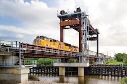
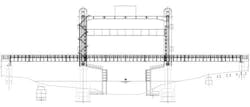
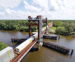
The new bridge design included the vertical lift span, plus flanking open-deck through-plate girder spans and ballasted concrete box approach spans to the main span, as outlined in Figure 1.
Construction and bridge details that would accommodate accelerated bridge construction controlled many design decisions. Placement and construction of the new piers, the need to pre-assemble major bridge components away from their final alignment, as well as a plan to remove the existing bridge and install the new bridge with limited impact to traffic drove many of the design details. Furthermore, advanced testing of the machinery and bridge controls, and preliminary balance calculations and measurements were required to expedite the time required for the bridge to become operable.
The final plan consisted of a two-phase construction approach. The first phase included building and installing the new piers adjacent to the existing piers under traffic on the same alignment. The second phase consisted of building major portions of the superstructure off-site and changing out the existing span while moving the new superstructure units to their final alignment during the traffic outage.
Construction and completion
Successful accelerated bridge construction projects have two distinct characteristics—thorough project planning and execution of the plan.
Project planning generally includes determining accelerated bridge construction means and methods; developing advanced plans and schedules; pre-assembly and advanced testing to minimize work during the traffic outage; and advanced preparation for the demolition of the existing bridge.
For the San Bernard River bridge, extensive planning was an ongoing effort. The new piers were constructed under traffic and adjacent to the existing piers along the final alignment. Although designers envisioned the span change-out to be accomplished by the float-in method, the phase two superstructure contractor chose to slide the bridge into place.
The contractor’s slide plan was dependent on adhering to the planned traffic outage and erecting it on falsework adjacent to the final alignment. It required the lift span to be erected atop the south approach span. Secured to four trollies and connected to an added rail fastened to the tower girder bottom flange, the lift span would be launched through the tower and connected to the counterweight ropes, then lowered into position by manipulating the counterweight prior to sliding the entire structure into place.
Due to the compressed timeframe, the details of the slide method were refined throughout the second phase of the project, and all stakeholders provided extensive input. Progress meetings and coordination with all interested parties were paramount to successful planning of the project.
To erect the new structure, temporary piles and falsework were constructed, which also supported the slide metalwork. First, the north approach TPG span was erected, followed by the south approach TPG span. The trackwork was installed on both approach spans. The lift span metalwork was erected atop the south approach span following track placement on the north and south approach spans. The lift span was eccentrically positioned over the south approach to prevent interference between the lift span and tower metalwork during the launch sequence. The trackwork was installed by the contractor following erection. The tower and counterweight boxes were the final elements of the steel structure to be erected onto the temporary falsework.
Prior to shipping to the bridge site, the design required primary mechanical drive components assembled and tested in a machine shop. This advanced testing was crucial in providing assurance of safe and reliable operation during the span change-out period. On delivery to the site, the machinery was installed atop the tower and aligned within allowable construction tolerances. Components were secured with temporary undersized bolts ahead of the bridge changeout.
The primary electrical installation included railroad communications and signals; all electrical power and controls work on the new bridge; and commercial power service. Placement of conduit supports and conduits; conductor and raceway installation; and placement of junction boxes and control cabinets were completed in preparation for the span changeout. Like the bridge machinery, the primary electrical drive components were required to be tested prior to being installed on the bridge.
Execution
For successful execution, all participants must understand and follow the steps developed in the planning phase. Additionally, all significant equipment should be tested for proper function and condition. It is equally important to have contingency plans to maintain the required schedule should an unplanned setback occur. Sequence alternates, on-call skilled labor and services, spare equipment, and spare parts are essential to accelerated bridge contingency plans.
Prior to the traffic outage at the San Bernard River, detailed plans and steps were developed, and everyone was assigned their respective task. The contractor employed two shifts of several crews at 12 hours each to execute the span change-out. A backup, barge-mounted crane was positioned downriver as part of the contractor’s contingency plan to be able to raise and lower the bridge should the bridge machinery be inoperable beyond the traffic outage period. Spare parts, an on-call machine shop, and a backup generator were also part of the construction contingency plan.
To execute the span launch, the trollies and a winch pulled the lift span into position between the two towers. The trollies and trolley rigging were installed ahead of the span-launch sequence. The span change-out and traffic outage followed the launch.
During the rail outage, the existing swing span was demolished. Each section of the span removed was prepared with staged rigging prior to the start of the outage. Demolished bridge sections were removed and placed on a barge.
During the demolition work, the contractor prepared the new bridge for the lateral slide operation. The jacking system used for the slide was placed and hydraulic jack hoses attached. Six 25-ton jacks were placed at roller locations. A synchronous power unit operated the six jacks and prevented any one jack from stroking ahead of any other. All jacks extended at the same rate and distance. As a backup, marks were placed along the slide track to ensure the bridge remained in line during the slide. Following the demolition of the existing bridge, the new bridge was slid into place. Union Pacific forces immediately installed the necessary materials and equipment to provide railroad signals and communication to the bridge. Men and equipment were cleared from the bridge deck, and Union Pacific reestablished rail traffic.
Machinery and electrical installation continued under rail traffic for the next 72 hours in order to restore marine traffic. Engineers checked machinery alignment and span balance for deviations from the allowable construction tolerances and made necessary adjustments. The bridge operated on the auxiliary drive motor for the initial lift of the span, and marine traffic was restored on time.
Following the traffic outage, remaining bridge components not integral to traffic operations were installed. The electrical controls system was debugged and made fully operational, and machinery alignment and bridge balance were improved to be within acceptable long-term running tolerances.
In the end, the bridge was completed on time with minimal impact thanks to using this accelerated bridge construction method.


