On the side of a mountain
Colorado. Hearing the name of this great state brings to mind images of snow-capped peaks, clear mountain water used to brew Coors beer and the soft melody of John Denver’s timeless song, “Rocky Mountain High.”
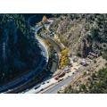
One of the primary benefits of living in Colorado is the availability of so many natural and recreational resources in the mountains, though accessing these resources has at times been quite frustrating. Popularity of our mountain hot spots, coupled with I-70 being the only straight shot that accesses them, can turn an hour-and-a-half pleasure cruise into a four-plus-hour nightmare.
I-70 is the only east-west interstate to cross Colorado and the only continuous east-west highway for accessing established communities along it, as well as recreational areas that are so important to the quality of life and economic base in the state. Destinations along the corridor include major ski resorts, quaint mountain towns and national forests that attract local, national and international visitors. Recreational travel is the most predominant contributor to peak corridor traffic, especially during summer and winter weekends and holidays. During the summer months, eastbound travel in late afternoon on Sundays is the highest travel demand through the Twin Tunnels area, with peak travel at the same time during ski season running a close second.
With foresight of the need for mobility enhancement, as well as a keen awareness of the time required to implement mobility improvements, the Colorado Department of Transportation identified the I-70 Mountain Corridor as one of 28 strategic projects funded by state Senate Bill 97-1 (known as the 7th Pot). A notice-of-intent to develop a Programmatic Environmental Impact Statement (PEIS) was published in January 2000, with a record-of-decision (ROD) approved in June 2011 following a decade of intense public scrutiny and stakeholder involvement. The PEIS (a Tier 1 NEPA process) determined that a multimodal transportation solution was required to meet mobility needs. Subsequent Tier 2 NEPA processes identified specific projects, with their own purpose and need statement, which would be developed consistently within the framework of the Tier 1 PEIS.
The Twin Tunnels project was the first major improvement (Tier 2 process) of the I-70 Mountain Corridor following the ROD for the I-70 PEIS. The goal of this project was to improve safety and mobility in the corridor in the vicinity of the Twin Tunnels just east of Idaho Springs, Colo. The project extended from milepost 241.4 at the east Idaho Springs Interchange on the west side of the tunnel to milepost 244.5 at the bottom of Floyd Hill on the east side of the tunnel where it tied into an existing three-lane section. The eastbound tunnel bore and highway was widened to include a third lane for enhanced mobility. The westbound tunnel bore widening and adjacent rock cuts were added to the project when additional funding materialized. However, westbound capacity improvements in the corridor have been deferred to future projects, pending further determination of a corridor-wide design speed. The original Twin Tunnels contribute significantly to the reduction in roadway capacity because of the “black hole” phenomenon on driver behavior, whereby drivers slow due to the narrow width of the existing tunnel, the blunt headwall configuration of the portals and the poor lighting contrast inside the tunnel.
A single season for each
Planning for this corridor improvement was based, first and foremost, on maintaining existing traffic capacity and minimizing disruption to the travelling public. Detouring eastbound travel onto adjacent County Road (CR) 314 was required in order to take the eastbound tunnel out of service while it was widened. For the westbound tunnel, eastbound traffic was again detoured onto CR 314 while westbound traffic was detoured through the newly widened eastbound tunnel.
The construction duration was selected to be a single season for each of the eastbound and westbound tunnels, with work occurring on-site between April and mid-December to minimize the impact of the project on travel demands in the corridor. Such an aggressive construction schedule required intense logistical planning by the design and construction teams, as well as a formal risk-sharing methodology because the risk increased proportionately with the aggressive schedule.
The project was delivered using the CM/GC alternative delivery process with contractor Edward Kraemer & Sons/Obayashi Joint Venture (KOJV) retained to work in parallel with the design team to provide real-time pricing and constructability advice. Project risk management was handled formally with the owner, contractor and engineering team holding workshops early on in the process to identify project risks; evaluate the severity of the risk in terms of cost, schedule or other suitable metric; and assign specific risks to the party best able to mitigate it. The risk register document was contractually binding on all parties. The CM/GC arrangement allowed both the contractor and designer to focus on project outcomes that not only could be built in a cost-effective manner, but more importantly could be implemented successfully under the demanding construction schedule.
Addressing the twins
The centerpiece of the project was the widening of the original Twin Tunnels, completed in 1961. The existing tunnel cross-section in each direction consisted of a 32-ft-wide opening, accommodating two 12-ft travel lanes and 2.5-ft shoulders adjacent to half barriers. The new roadway typical section includes three 12-ft travel lanes, a 4-ft inside shoulder and a 10-ft outside shoulder for a total roadway clear width of 53 ft, including the half barriers.
The new eastbound tunnel cross-section was positioned such that the left (when looking east) exterior face of the new liner cross-section was poured against the inside face of the existing liner. The existing tunnel liner along the left edge from footing to springline remained in place. This benefited the project by minimizing the amount of the existing tunnel liner that had to be removed and placed all of the excavation for widening on the south edge of the existing tunnel.
For the westbound tunnel, KOJV proposed lowering the profile grade of the roadway approximately 2 ft to retain even more of the existing tunnel liner as temporary excavation support, providing a cost savings for the project. The center rock pillar between eastbound and westbound tunnel bores was investigated to determine if it could handle the additional load imposed from the widened tunnel sections, and fortunately these investigations concluded that adequate load capacity existed. Rock bolts were installed in the center pillar to minimize the potential for deformation of the existing westbound tunnel liner while eastbound bore construction progressed.
The excavation scheme for construction of the new tunnels consisted of drilling and blasting methods typical for mined tunnels. The in-situ rock quality varied along the length of the tunnel, so the length of the excavation occurring in a single blast varied based on the rock’s ability to stand on its own while temporary ground-support measures were installed. Temporary ground support within the tunnel consisted primarily of steel channels, arch dowels, spiles and shotcrete. Temporary ground support at the portals consisted of W-section steel sets.
The proposed tunnel cross-section shape was selected based upon pre-existing steel forms used to cast ConSpan concrete arches. Precast concrete liner construction was considered early in the process of tunnel design, but ultimately the most cost-effective alternative was to cast-in-place the tunnel liner using a rolling tunnel form mounted on rails. Rebar cages were prefabricated outside the tunnel using a stationary rebar gantry and rolled into place with the tunnel form.
Clear answer
Very tight horizontal curvature and a history of accidents necessitated the replacement of the I-70 eastbound Clear Creek Bridge. The difficult site presented many design challenges, which required consideration of multiple unique features. The resulting three-span bridge incorporates integral abutment and pier fixity, post-tensioned pier caps, uplift considerations due to poor span balance and skew, erection sequence considerations, micropile and drilled shaft foundations, and mass concrete.
Precast, prestressed concrete girders were used in a chorded layout for the structural framing. Structural steel girders were not considered due to the schedule risk of fabricating and delivering steel girders under the aggressive, single-season construction deadline for eastbound I-70. Erection of the bridge girders for the middle 155-ft span required two cranes, with one positioned immediately behind one of the piers to minimize the required reach. Integral pier caps were used in combination with single column bents to eliminate the visual mass and clutter associated with a traditional mutlicolumn bent with drop pier cap. This opened up the riverbank areas for recreational access.
Forming a wall
Over 4,400 linear ft of retaining walls were used to support the roadway widening. Most retaining walls were fill walls, but a couple of cut walls with top-down construction using soil nails were required as well. Investigations into various wall types concluded that cast-in-place concrete cantilever, semi-gravity walls on spread footing foundations was the most cost-effective wall type and method of construction. Global stability was investigated extensively for wall sections adjacent to Clear Creek. Excavation of the existing highway fill for eastbound I-70 was limited in some places in order to provide a minimum clear width for construction equipment traveling within the project site.
What makes it beautiful
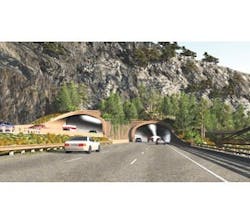
The tunnel portal extensions comprise the longitudinal extension of the tunnel structural cross-section beyond the rock face (known as a turn-under point) out to the free edge of the structural cross-section at each end of the tunnel. The tunnel portals form an important multidiscipline interface encompassing geotechnical, structural, aesthetic, traffic and lighting considerations.
The primary function of the tunnel portal extensions is to shield tunnel users from rockfall potential. Rockfall potential at the east portals was minimal due to favorable properties of the rock mass above the tunnels. Rock potential at the west portals was substantial due to the geometry of the mountainside and unfavorable properties of the rock mass. The length of the tunnel portals was determined based upon the probability of capture of rockfall from all potential sources. The length of the westbound west portal was set at 110 ft and the eastbound west portal at 82 ft, with a rock catchment basin situated atop the two portals to further attenuate a rockfall incident.
A secondary function of the portals is to provide a visual transition between the open roadway cross-section and the confined cross-section within the tunnel, particularly as it relates to driver perception. Lack of this transition with the existing blunt portals causes drivers to hesitate when entering the tunnels, which results in a slowing of traffic through the tunnel and a reduction in highway capacity. Traffic backups are common because of this phenomenon. Lighting of the tunnel entrance is an integral component of this transition as it can greatly affect driver perception (and therefore behavior) when approaching and entering the tunnel. A state-of-the-art LED lighting system was included in the new tunnels to further mitigate the black-hole effect.
The portals serve as a significant visual element of the landscape. They are the only visual element to define the aesthetics of the tunnel, since all other elements are hidden within the structural lining of the tunnel. The overall project development process included consideration of aesthetics in every element of the construction, but the tunnel portals received the bulk of the effort to integrate all disciplines into a visually pleasing configuration.
“Functional considerations for roadway mobility, rockfall mitigation, noise attenuation and access for maintenance equipment drove the design for the portal configuration, culminating in the spiral transition runout walls visible to drivers,” noted Kevin Shanks with THK Associates, lead landscape architect for the project.
It has taken 17 years to produce a measurable benefit to individual mobility on the I-70 Mountain Corridor. The widening of the Twin Tunnels has relieved the corridor of its worst bottleneck. From all perspectives the project was quite challenging but also very rewarding, resulting in a public asset that benefits the entire traveling public. The enhancements to safety and mobility will serve the traveling public for many decades, resulting in low life-cycle cost and a high level of satisfaction for corridor users. R&B