Restoring a landmark
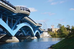
A 100-year-old fixture in its community, the Kenneth F. Burns Memorial Bridge carries Rte. 9 over Lake Quinsigamond between Shrewsbury and Worcester, Mass.
The previous concrete arch structure carried four lanes of traffic—two eastbound and two westbound. Prior to that, the crossing was originally built as a floating bridge of logs chained together to carry the wagons and stage coaches on the Boston-Worcester Turnpike. The new replacement bridge consists of two independent structures: one carrying eastbound traffic and the other carrying westbound traffic. But redesigning the bridge for today’s needs didn’t come without challenges—from its long, flat profile to avoiding disruption of the busy and crucial Rte. 9 corridor.
Approaching the design
Both of the replacement structures are five-span, post-tensioned, steel deck arches with a total length of 870 ft and a main span of 240 ft. The roadway slab is supported by stringers, floorbeams and columns above the main arch ribs. Each structure uses three arch ribs in order to provide redundancy of the arches.
The arches are relatively shallow, with a rise-to-span ratio of about 1:13. These arches tend to generate more lateral thrust than would be produced by deeper arches. In fact, the arches are flat enough that, in some respects, the behavior begins to approach that of a beam rather than an arch. For this reason, the design takes advantage of moment continuity of the arches at all four piers.
Soil conditions at Lake Quinsigamond are such that lateral thrust from the arches cannot be resisted by the subgrade. Therefore, the structure has been designed as a tied arch. Tension ties are provided by a redundant system comprised of post-tensioned ties and steel stringers.
The combination of the flat arches and the tied arch design has two main effects on the structure. First, it exhibits a hybrid behavior with characteristics of both arches and beams. This results in relatively large bending moments in the arch ribs, as compared to a compression arch where axial force dominates. Second, the stringer and deck system attracts a significant amount of tension as the arches spread due to gravity loads. Along with this second effect come large shear forces where the columns and floor beams connect to the arches.
A post-tensioning system helped to address both of these challenges. The dead-load bending moments in the arch ribs were reversed by post-tensioning the arches before the deck was poured. The pre-compressed arches have significant compression and minimal bending under dead load at the end of construction. The tension forces in the stringers were offset by applying some of the post-tensioning force to the stringers. Pre-compressing the stringers in this way decreased both the final stringer tension and the associated connection forces.
The four pier foundations were designed using a perched approach in which the bottoms of the piers sit below the water level but above the lake bottom. This was accomplished by building a watertight form, pouring the bottom portion of the pier as a soffit with blockouts to accept the piles, setting the pier soffit and formwork on the piles, sealing and dewatering the formwork, and pouring the remaining pier concrete. The whole pier construction assembly, including formwork and pile reinforcing steel, was then floated out on barges to its final location. This approach resulted in substantial scheduling and cost advantages because it eliminated the need to work within cofferdams in the lake. Environmental impacts due to potential dredging also were minimized.
Aesthetics and detailing
The previous Burns Bridge was not just a functional crossing, but an iconic structure appreciated as a part of the landscape for almost a century. It crosses a waterway with heavy recreational use in all four seasons. For much of the year, the lake is a center of rowing and sculling, and it is used to host national competitions. With so much value to the community, it was important from the start of the project that the new bridges be not just functional, but also beautiful.
The new bridges are detailed as steel deck arches that respect the arch form of the old bridge but in an updated version that is more open and graceful. The new bridges have larger vertical and horizontal clearances under the arches, which provide opportunities for bigger boats and improved staging of race events. Some aesthetic features incorporated in the design include:
- A customized pedestrian handrail;
- Pedestrian lookouts, located at each abutment and pier on both structures, for viewing sculling competitions and other water events;
- Architectural roadway lighting coordinated with revised lighting in Worcester and Shrewsbury;
- Smooth, uncluttered fascia designs on the box beams, with special details for the post-tensioning conduits to limit their visibility. The designers took advantage of visualization and daylight/lighting studies to optimize this appearance;
- Design for continuity across piers to emphasize the horizontal sweep of the bridge structure;
- Development of portal architectural “sail” sculptures at each bridge approach to help frame the bridge and lake views; and
- Design of variable color LED up-lighting for the below deck arches and the sail sculptures.
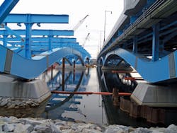
Looking east: Eastbound bridge in service, westbound bridge under construction.
Construction
Rte. 9 through Massachusetts is not only a busy major corridor, but also an important community connector in this part of the state. The Burns Bridge is central to that connection, meaning the traffic impacts of its reconstruction had to be minimized as much as possible. To do so, the project team employed a design-build approach under the Massachusetts Department of Transportation’s Accelerated Bridge Program.
As stated, the previous concrete arch structure carried two eastbound and two westbound lanes of traffic. The overall sequence of construction was to: 1) construct the new eastbound structure adjacent to the existing bridge; 2) temporarily shift both eastbound and westbound traffic onto the new eastbound structure; 3) demolish the existing structure; 4) construct the new westbound structure in the place of the existing structure; and 5) divert westbound traffic onto the new westbound structure.
The staging sequence required construction with tight clearances as the new eastbound bridge was built only a few feet south of the old concrete structure. Early in construction, the cantilever sidewalk on the south face of the old bridge was demolished to provide more room for construction.
To negotiate these tight clearances and develop the construction sequence, the project team created a three-dimensional, staged-construction analysis of the proposed structure. The structure was modeled using CSI Bridge design software. The model also included the effects of soil-structure interaction at the four piers. This was modeled using nonlinear P-y curves varying with depth along each pile.
This level of modeling was necessary for a structure as complex as the new Burns Bridge. In the case of a typical girder-slab bridge, the effects of locked-in stresses can be computed by simpler methods; e.g., by hand. In the present case, the large number of construction steps coupled with the hybrid arch-beam behavior of the arch ribs, the tendency for the stringer/deck system to attract tension, and the presence of the post-tensioning system required a more sophisticated analysis approach.
The staged-construction analysis was particularly important to the design of the post-tensioning sequence. The objective of the post-tensioning was to minimize both the arch rib bending moments and the stringer axial tension at the end of construction. The objective of the post-tensioning was therefore evaluated at several significant stages (such as deck pours) after the post-tensioning was complete.
The actual post-tensioning procedure used two stages. First, 500 kips per tendon was applied before stringer connections were made. An additional 500 kips per tendon was applied after the stringer connections were made. The total force and the distribution between the two stages of post-tensioning were selected with the aid of the staged-construction model.
That extra dimension
In addition to the staged-construction analytical model, a three-dimensional model of the proposed Burns Bridge and its surroundings was created using Autodesk’s AutoCAD and 3ds Max visualization programs.
The main purpose of creating 3-D models was to provide an accurate visual representation of how the replacement bridges would look upon completion. Being able to produce renderings of the proposed design was useful through the entire duration of the project, from the beginning of the design proposal when the bridge-type selection process was underway through the 100% design submission when details of the bridge were being finalized, and even during construction to assist with critical architectural detailing. In addition, the 3-D model was used to validate the design as it was shown on the contract drawings, to check for utility conflicts or other geometric interferences, to convey the overall design to the general public and vested stakeholders, and to make numerous aesthetic design decisions.
One typical example of use of the 3-D model was to evaluate geometric constraints for post-tensioning. It was determined that planned multi-strand jacks could interfere with some of the stringers. To investigate this potential conflict, the post-tensioning jack was modeled according to the fabricator’s drawings and then imported into the global 3-D model. The model of the jack was then positioned as it would be in the field during construction, and a geometric interference check was performed. This analysis indicated that the jack would interfere with the stringers at four different locations. By using the 3-D model to identify the locations and magnitudes of the interferences, the designers were able to provide for stringer modifications to avoid the conflicts.
The 3-D model also was heavily relied upon when making aesthetic design decisions. By providing a way to see how various components would look from different perspectives and alongside other members of the bridge, the design team was able to make educated decisions on important aesthetic factors. Visualization was used to evaluate the aesthetics of the architectural sails, the concrete end posts, the gateway bumpout layout, the positioning of the post-tensioning tendons, the aesthetic lighting of the sails and arches, the median design, and the landscaping design, among many other details.
Dedication
Construction of the new Burns Bridge achieved substantial completion in August 2015, four months ahead of schedule. The community celebrated its opening at a dedication ceremony on Nov. 1, 2015. At the ceremony, Massachusetts Lt. Governor Karyn Polito stated, “It’s a perfect bridge for our times and for our future, connecting communities both above and beneath the bridge span.”
Feedback on the bridge and the project has been uniformly positive. Traffic flow on Rte. 9 and Lake Avenue is greatly improved. The bridge, with its graceful leaping arches, sail sculptures and dramatic lighting, has quickly assumed “icon” status in the Worcester area.