Dial, collect. Dial, collect. Dial, collect.
HNTB Corp. wasn’t out of change, and they certainly weren’t short on ideas. But calls had to be made, information gathered.
Before pulling a chair up to the design table, HNTB locked into a pre-planning stage of the Storrow Drive Bridge, which is part of the Central Artery Tunnel Project in Boston. People were contacted, industry people. Steel fabricators, steel erectors, detailers and just about anybody else in the bridge building phone book. The goal was to gather as much input as possible, and asking the right people the right questions wasn’t always easy.
"It’s a little more than just calling people. It’s knowing what you need to ask when you call," Sena Kumarasena, P.E., project engineer/deputy project manager of the Storrow Drive Bridge, told ROADS & BRIDGES. "Other than the nuts and bolts issues I would say that’s the most significant thing about this project . . . getting input from the industry. You get answers, then you think about it a little more and ask follow-up questions and try to get even more information. We tried to get the market to work for us."
And in the end it worked for the better . . . make that the best. The Storrow Drive Bridge received the 2000 George S. Richardson Medal at the International Bridge Conference in Pittsburgh on June 12. Presented by the Engineers’ Society of Western Pennsylvania, in association with ROADS & BRIDGES, the award marks a single, recent outstanding achievement in bridge construction.
"This project is worthy of it, it’s a fitting award," said Kumarasena. "It showcases some of the industry’s capabilities."
Everyone involved came out looking like skilled mountain builders. The Storrow Drive Bridge is one of the largest single-cell trapezoidal steel box girder bridges in North America. And the city of Boston needs every square inch. The four-lane span is part of the I-93 river crossing, which is perhaps the most congested area in Beantown. It’s also known to have one of the highest accident rates in the country.
No other alternative
Two designs—one steel, one concrete—were submitted for the Storrow Drive Bridge. Both involved a single-cell box girder and faced a stern project constraint. The pier widths could only be 18 ft wide at the top.
"We looked at other things than the single box girder," said Kumarasena. "However, some of the other solutions didn’t quite match the restrictions that the project had for this bridge."
HNTB glanced at the possibility of using two boxes, but that would force the width of the box at the base to be too narrow, thus wasting steel. It also called for the floor beams to be extended, requiring additional splices.
Another demand was visual compatibility with an adjacent main line cable-stayed bridge. The two groups also had to deal with fixed pier locations and span ratios.
The overall bridge layout consisted of a three-span structure measuring 830 ft in total length with a main span of 380 ft. The superstructure supporting the 76-ft-wide roadway is supported on a variable depth box girder 18 ft deep at the main piers.
For concrete, those conditions were favorable. HNTB, however, turned the steel design into the economical choice. The construction contract was awarded to Daniel O’Connell (DOC), Holyoke, Mass., for $22.3 million. Tampa Steel was the selected steel fabricator and one of the few who suggested fabricating the entire 830-ft-long box girder in sections and delivering them by ocean-going barge.
"It’s really common in segmental concrete boxes to have a box that big, but it’s really rare for a steel structure to have a box that big," said Kumarasena. "Normally you go for smaller boxes and you wouldn’t even think something like (a steel box girder) would work."
This calls for an idea
When the design hit rock bottom, new challenges erupted. While examining the rock-core data from geotechnical investigations, the rock profile in the area was found to be highly variable, consisting primarily of intermixed layers of rock deposits of Silty Argillite and Clayey Argillite. The soil conditions also indicated the presence of liquefiable layers at the riverbanks near end piers.
On the rock variability issue, HNTB decided to deal with the problem as the bridge was being constructed. The flexible approach allowed the contractor to make a core boring when necessary, determine what is really variable at that particular location and make the correct adjustments.
"If you did a rock core and examined the properties at one location, then did it at another the results could be very different," said Kumarasena. "The information we had readily available during the design phase wasn’t necessarily accurate."
Drilled shafts 8 ft in diameter turned out to be the solid choice for the liquefiable layer issue. The strategy was to make the shafts strong enough to resist the flow of the soil. At the south end of the pier, where liquefaction was more significant, the shafts are protected by a 10 1/2-in. permanent steel outer casing and additional reinforcing steel.
"It was the first time that that approach was taken," said Kumarasena.
The size of the box and transportation difficulties called for the creation of another design innovation—optional longitudinal splices. The normal field splices were provided to sector the 830-ft girder into nine separate field sections. The optional longitudinal splices sub-divided the sections into as many as four pieces, according to Kumarasena.
Everything was brought together in two segments. The contractor lifted the lower half up first, tied it down on the pier and then placed the upper half. In order to align the webs correctly, splice blades were raised.
In feet and inches
The main steel box girder measures 34 ft, 6 in. out-to-out of top flanges, and varies in depth from 8 ft at the end piers to 18 ft at the main piers and 10 ft at the center of the main span.
The variable depth girder is 31 ft wide at the top flange level. The constant web slope and the variable depth results in a bottom flange width of 18 ft at the main piers to a maximum of 25 ft at the end piers. The 76-ft roadway width is achieved by using floor beams with cantilever outriggers extending out a typical distance of 17 ft, 6 in. beyond the box girder. The entire floor beam measures 66 ft end-to-end and consists of three sections with one inside the box girder and two outer cantilever sections.
The outer ends of the cantilever outriggers also frame into a fascia girder, which varies in depth from approximately 1 ft to 8 in. at the center of the main span to a depth of about 5 ft at the end piers. The exact depth of the fascia beam at the end piers is set to match the structure depth of the abutting viaducts at the respective interfaces. In addition to its aesthetic function of providing a smooth transition and hiding utility lines from direct view, it also serves to distribute wheel loads in the longitudinal direction, optimizing the design of the cantilever outriggers.
The superstructure required 1,860 tons of structural steel. Over the main piers, the box section consists of 4-in. x 54-in. top flanges, 2-in.-thick bottom flanges and 1 1/4-in. web plates.
Over the negative moment regions near the main piers, the box girder bottom flange was stiffened with WT 16.5 x 100.5 welded in the transverse direction and six lines of WT 10.5 x 36.5 in the longitudinal direction, longitudinal stiffeners detailed to pass through web openings of the transverse stiffeners.
Over the positive moment areas, the longitudinal stiffeners were changed to 3/4-in x 8-in. plates with MC 6 x 11.5 used in the transverse direction connected to the longitudinal stiffeners at the top with clip angles.
The box girder field splices were made with ASTM A325 1-in.-diam. bolts. All other bolted connections used 7/8-in.-diam. bolts, including the optional longitudinal splices.
The two pot bearings atop each of the main piers have a capacity of nearly 5900 kips each. The expansion pot bearings at the end piers are nearly 1000 kips each.
The single column main piers taper from a 20 ft width at the top down to 16 ft at the base in the transverse direction. In the longitudinal direction, the shaft width is 9 ft, 6 in. at the top, increasing at a uniform taper with decreasing elevations.
The main piers are founded on 11-ft-thick, 36-ft x 36-ft footings supported by the drilled shafts.
The frame type end piers consist of a cap beam supported by two circular pier columns. The 7-ft, 3-in.-diam. pier columns also are supported by single drilled shafts concentric with the column.
The 10-in.-thick, 4500-psi concrete deck slab was designed to act compositely with not only the main box girder, but also with transverse floor beams, including the cantilever outriggers and the longitudinal fascia girders. The deck is finished with a 1 1/2-in. LMC overlay.
In forming the deck for the cantilever overhang and the outer sections between the box girder and fascia girders, removable forms supported by bar joists were used.
For the interior section between the webs of the box girder, SIP forms were allowed. To eliminate the increase in the additional dead load due to concrete in the 4-in.-deep troughs of the SIP forms, Styrofoam filler was used as cover.
The SIP forms were in turn supported by hanger rods extending down from temporary steel beams spanning transversely. The temporary beams were supported on a four-legged chair placed on the box girder top flanges, situating the beams about 2 ft above the finished deck slab.
Standing it up
After considering the availability and feasibility of lifting equipment, DOC planned to lift the field sections using a barge-mounted Manitowoc 4100 ringer crane and a land-based M250.
The 830-ft box girder was shop assembled from end-to-end, including the cantilever outriggers and the fascia girders, and surveyed to verify the cambered geometry. After the shop fit-up, they were disassembled and shipped to Boston by way of ocean-going barges.
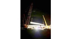
The south and north main pier segments were erected first on the permanent piers and stabilized by false work towers. The lower half was lifted into position, followed by the upper half. Then the remaining field sections forming the north and south back spans were completed.
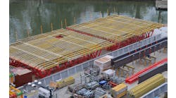
The three field sections forming the remaining 290 ft of the 380-ft main span were bolted on barges and floated into position. Next, the two ends of the back spans (at the end piers) were jacked up 30 in. above the final elevation on the permanent bearings. Temporary longitudinal movement also was permitted at one of the main pier fixed bearings so one of the back spans could be pushed back to provide adequate clearances during the lifting of the main span segment and then brought forward into position for completing the splice.
Jacking against the cantilevered ends of the main pier girder segments lifted the main section span into position. After the main span splicing was complete, the girder at the end of the piers was lowered onto the permanent bearings, inducing the proper negative moments at the final main span splice locations.
The temporary allowance for longitudinal movement at one of the fixed bearings was maintained until all of the dead load was affected on the bridge.
The jacking of the 650-ton main span section was accomplished by using a total of 20 jacks. Each carried a 50-ton capacity. The arrangement consisted of five jacks at each side of the two lifting frames.


