No ordinary bridge

The Illinois Tollway’s 15-year, $12 billion Move Illinois Program includes the 62-mile-long Jane Addams Memorial Tollway (I-90) Rebuilding and Widening Project.
The project is providing six reconstructed and expanded lanes from Randall Road in Elgin to I-39 near Rockford (completed in 2014), and the reconstruction and expansion to eight lanes from the Tri-State Tollway (I-294) to Randall Road, which will be completed in 2016. The new I-90 also will feature significant improvements to seven interchanges and accommodations for bus-on-shoulder service along the eastern segment in partnership with Pace Suburban Bus. The project necessitates that the crossroad bridges over I-90 be reconstructed with longer spans to accommodate the widened mainline section.
One such crossroad is Higgins Road (S.R. 72) in Hoffman Estates. The Higgins Road Bridges over I-90 are twin structures located approximately 30 miles northwest of Chicago. They span a heavily traveled section of I-90 that carries 118,000 vehicles per day. Each bridge cross-section consists of six equally spaced steel-plate girders which support the 49-ft 3-in.-wide cast-in-place concrete deck that is designed to carry three lanes of arterial traffic. Both bridges have two 280-ft spans with a total bridge length of 560 ft.
The most unique feature of these bridges is that the median pier and abutments are skewed 70°. The superstructure consists of 9-ft 6-in.-deep plate girders and includes full-depth diaphragms at the pier and abutments. The severe skew led to a complicated design that resulted in a unique framing arrangement and high lateral loads and displacements that must be resisted by the bearings and substructure.
Working askew
The first of the Higgins Road dual bridges was constructed in 1957, and as traffic demands grew, the second parallel bridge was constructed in 1978. Designers of the first bridge avoided the skew by providing squared-off abutments and a unique intermediate pier configuration. The piers consisted of two sets of steel transverse girders and steel tie girders, which were connected to form a square-plan layout. The transverse girders provided four intermediate supports but were considered fracture-critical members.
The designers of the second original parallel bridge utilized three continuous spans but decided to avoid the fracture-critical issues of the transverse support girders at the pier, and instead designed the structure with a 70° skew and a more traditional pier configuration.
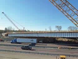
For the proposed bridges, various alternatives to minimize the structure skew were considered but were greatly constrained by the inability to alter orientation of the median pier and the dramatic increase in span lengths by squaring up the abutments. Reorienting the median pier would have required changes to the mainline horizontal alignment since the median shoulder width could not be locally compromised. The resulting increased span lengths from squaring the abutments also would lead to significantly more bridge deck area and increased structure depths that would have raised the profile on Higgins Road. Retaining walls would also have been required along the bridge approaches to stay within the Higgins Road right-of-way. Impacts to adjacent properties were especially sensitive, and property acquisition was not an option. Lastly, the volume of I-90 traffic required that all three lanes in each direction be kept open except during off-peak hours. Therefore, a two-span steel girder system with a 70° skew was selected.
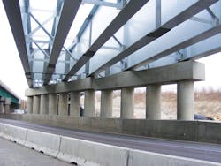
The 9-ft 6-in.-deep plate girders run across a 70° skew of the piers and abutments.
The six equally spaced steel girders support a 49-ft 3-in.-wide cast-in-place concrete deck.
Getting the right design
Due to the severe 70° skew and long spans, this structure required a refined 3-D analysis to properly account for force effects, displacements and rotations. Severe structure skew leads to displacements and rotations that are significant and must be accounted for in design, fabrication of the structural steel and during construction. For this bridge, steel dead-load fit was specified, which in turn defined the geometric relationship between the girders and cross frames. This fit condition provided acceptable geometric control and reasonable ease of erection. A conceptual erection plan was considered during the design phase to ensure structural stability and minimize assembly issues during steel erection. With significant traffic considerations, a shop assembly to verify fit-up was specified to minimize field erection issues.
Due to the span configuration, as well as the force effects due to skew, 9-ft 6-in.-deep, constant-depth girders were required to carry the design load. The girder depth could not exceed this amount due to vertical clearance requirements for I-90. To achieve economy with regard to fabrication and construction, all six girders used the same plate sizes and were symmetrical around the centerline of the pier. Due to the skew effects, the design requirements at mid-span did not vary greatly from the section adjacent to the abutment. Therefore, the same plate sizes were used for the entire positive-moment region. A field splice was used in this region to limit the member length to 120 ft for shipping and handling purposes. Plate widths were set to achieve a b/t ratio of ≤ 24 (per AASHTO LRFD Bridge Design Specifications) for the most economical size to carry the induced stresses due to major- and minor-axis moments.
For the stockier, negative-moment region of the girder, which is 124 ft long, flange transitions were located 20 ft on either side of the pier centerline to economize the girder. For ease of fabrication, the flange width remained constant throughout the 124 ft length, and the width was set to limit maximum flange thickness to no more than 3 in. (for plate availability purposes).
The web thickness remained constant throughout the girder’s entire length and was sized large enough to eliminate the need for transverse stiffeners beyond those used as cross-frame connection plates. The steel framing employed discontinuous cross-frame lines in most locations along the length of the bridge. The discontinuous cross-frame lines effectively mitigated potentially stiff transverse load paths and such paths’ commensurate effects in these regions, thus reducing the forces carried by the cross-frame members.
High-load, multi-rotational bearings were required for the Higgins Road Bridge due to the long span length and severe skew. Disc bearings were specified. While pot bearings were considered, it ultimately was determined they were not a practical alternative for this particular bridge. Pot bearings can typically accommodate up to 0.05 radians of rotation. The design rotation at the abutments was in excess of 0.07 radians. Out-of-plane rotations (about an axis parallel to the girder web) were significant, caused by both dead load and live load. A combination of fixed bearings, guided expansion bearings and non-guided expansion bearings was provided, with all four fixed bearings located at the pier. Horizontal reactions at the four fixed bearings were significant and were challenging to manage in terms of pier design.
Dropping the deck
A deck-placement procedure was specified in the contract plans. The transverse construction joints were placed to be parallel with the skewed supports, and the end spans were to be placed before the concrete over the pier went in. Placing the concrete deck in this sequence helped to reduce the potential for deck cracking in the negative-moment region. Concrete was placed along the skew to the fullest extent possible, and any advance concrete placement was made with the use of a retarding agent. Placing the concrete along the skew results in similar loads and length of loads applied to all girders, therefore not exacerbating the differential deflection results related to the skewed supports.
Placement of the concrete deck was considered in the design of the girders for both checking the girder constructability-limit state per AASHTO LRFD and for determining the girder camber. The 3-D finite-element model was utilized to investigate the deck-placement sequence. For this structure, the dead-load deflection due to concrete varied significantly between the deflection assuming a single monolithic deck pour and the accumulated deflection due to the deck-placement sequence. Therefore, the girder camber, due to concrete dead load, was based on the deck-placement sequence and was noted as such in the contract drawings.
Additionally, the deck-placement sequence was checked to verify that maximum tensile stresses in the deck after each stage were less than 0.90 times the modulus of rupture of the concrete. Using the 3-D finite-element model, stress in the concrete deck was tracked for the three stages of the deck-placement sequence. Verifying these deck stresses resulting from the deck-placement sequence helped reduce the potential for cracking of the concrete deck during deck placement.
Joint & pier
A swivel-type modular expansion joint was specified at each end of the deck. The governing effect was the racking, which is the movement along (parallel to) the modular joint. Because of the bridge’s 70° skew, the joint was nearly parallel to the longitudinal direction of the bridge, so large movements parallel to the joint were expected. The main contributor to movement in the longitudinal direction of the bridge would be thermal movement.
Because of the twisting effect of the bridge caused by the severe skew, movement in the transverse direction of the bridge at its ends will be more significant than in bridges with less skew. To minimize movement to which the joint will be subjected, the modular joint was specified to be placed after all main deck pours were completed, just before the closure pour was to be made at the end of the deck.
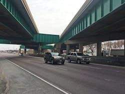
A two-span steel girder system with a 70° skew was selected to minimize the impact to adjacent properties. Pictured are the original 1957 bridge (left) and the 1978 bridge that cross I-90.
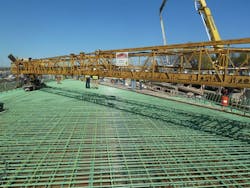
Deck placement was analyzed using a 3-D finite-element model, which tracked concrete stress across all three stages.
A multi-column, conventionally reinforced concrete pier was selected for the median support of this two-span structure. Various configurations were considered for the pier, and the final design consisted of three pier segments: the first segment to support girders 1 and 2, the second segment to support girders 3 and 4, and the third segment to support girders 5 and 6. The cap consisted of a rectangular section, 5 ft 6 in. wide and nominally 4 ft 6 in. tall. Eleven circular columns, each with a 4 ft 6 in. diam., were provided at the pier with one column under each girder line and an additional column in between each girder line.
The three pier segments share a continuous crashwall and pile cap. The crashwall extends 5 ft above the proposed roadway top, at a minimum overall height of 6 ft. The pile cap is 4 ft deep and 17 ft wide, supported by four rows of battered HP14x73 piles. Although the appearance of the pier from the outside may seem fairly ordinary and conventional, the design challenges and detailing of this pier were unique. The foundation design consisted of four rows of piles battered at 3:12, which is the slope of the pile as driven (3:12 = 3 in. horizontal per 12 in. vertical).
Because of the severe skew and long spans, the four fixed bearings at the pier bear very high horizontal forces due to a combination of thermal effects from the superstructure, dead load and live load. Because of the high horizontal forces and in particular because the horizontal forces vary in magnitude from bearing to bearing, torsion in the cap is very high. Torsion and lateral bending (bending of the cap in the horizontal plane) were the main factors in the pier design.
One of the unique challenges of the pier design was the anchorage reinforcement at the fixed bearings. A specialized approach was necessary, which included seismic-like detailing. The special detailing in the cap was further complicated by the presence of 16 anchor bolts at each fixed bearing. Because of the reinforcement congestion in the cap at the fixed-bearing locations, a 3-D parametric model of the reinforcement was created to ensure that bar clearances were sufficient and to aid in constructability checks.
Final word
In result of all this painstaking pre-construction design work, the first of the twin Higgins Road Bridge structures, coming in at a price tag of $22.7 million (which equates to approximately $390 per sq ft), opened to traffic in June 2015. R&B