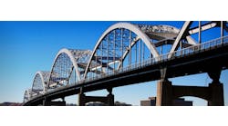
The South Road Superway is a new elevated highway currently under construction in Adelaide, South Australia.
The city of Adelaide is oriented mainly along a north-south axis, with the ocean running along the western edge of the city. Currently, there is no continuous limited-access highway that runs the length of the urban area.
The South Road Superway is a building block in establishing just such a corridor. In the long term, the South Road Superway will link up with several other projects—some complete, some planned for the future—that will provide high-speed roadway access from the southern suburbs to the northern highways and beyond.
In the short term, the Superway will serve as critical congestion relief in the northern end of the city. The Superway is located in an industrial area, where access is permitted for the large Australian triple-tandem trucks. It will provide direct access for these trucks and other traffic from the northern part of the city to the highways connecting Adelaide to Sydney, Melbourne and other Australian cities.
The Superway is a total of 2.8 km long and has twin carriageways along the entire length. Each carriageway can carry either three or four lanes of traffic, and there are on- and off-ramp structures at two locations.
The South Road Superway is owned by the state of South Australia and is administered by the Department of Planning, Transport and Infrastructure, commonly known as DPTI. The project is being delivered under a design-build contract, with the construction joint venture as a consortium of John Holland, Macmahon and Leed, three major Australian contractors. Their design team is led by GHD and is supported by SMEC and International Bridge Technologies.
Super challenge
The entire elevated structure is being built with a precast segmental superstructure. Typical spans are 66 m long and are built in balanced cantilever. The segments are constant depth, bringing a uniform appearance to the entire viaduct. The expansion joints are at midspan and employ steel needle beams across the joints to provide continuity for moments and shear, while allowing longitudinal expansion. This is the first application of this type of joint in Australia.
The piers are both architecturally interesting and structurally challenging. Both carriageways rest on a single curved, Y-shaped pier. The superstructure is monolithic with the substructure, and the top of the Y is tied together with a post-tensioned cross beam. This basic structural scheme is carried through all of the varying roadway conditions encountered along the alignment, from the standard three-lane portions, the ramps and gore areas and into the wider four-lane box girders.
The design was performed under the Australian standards. This required a careful review of the governing codes, as in some cases they differ significantly from the American equivalents. In addition, there were some aspects of the structure itself that presented unique engineering challenges.
Aussie rules
When working abroad, it is always important to keep a close eye on the assumptions that the designers bring to the project, as the code environment may vary from one country to the next. In Australia, the first challenge was clarifying which alignment was northbound, and which southbound (not always easy for American designers to remember).
Apart from cultural differences, it was quickly apparent that the Australian code differs from the American code in fairly significant ways and in general is more conservative. The Australian code is known as the AS5100 and is part of the national standards for Australia and New Zealand.
As part of the design development, various results calculated per AS5100 and the AASHTO LRFD were compared. There are many differences, but the most striking is live loading. For the same structure, after all multiple lane factors and impact factors are accounted for, the resulting Australian live load is approximately double the AASHTO result. This difference is not alleviated by strength load factors, which are generally equal or slightly greater in the AS5100.
In addition, the allowable stresses for service cases are generally more stringent, and the service load combinations tend to include more load effects into a single combination (e.g., including full differential temperature with live load). On the strength side, the phi factors are generally lower by 0.1 or more. Each of these differences has a cumulative effect, the net result of which is a noticeably more conservative design, with higher material ratios than typically seen when designing to AASHTO.
Piers with a flare
The project will serve as a gateway to the northern end of the city of Adelaide and as such is architecturally important. The owner clearly desired a structure that would have a positive aesthetic impact on the site and did not want a “cookie-cutter” design. One of the primary ways that this was expressed was in the design of the piers. Each pier begins with a single, central stem, generally located within the median of the existing South Road. After a section with a constant width, the legs of the pier split apart, and dramatically flare outward. The outside edges of the superstructure box girders align with the tips of the flare, and the two legs are tied together at the top with a curved, post-tensioned beam.
While striking in appearance, this configuration does present several design and construction challenges. When designing the piers, it is important to recognize the effects of the curvature on the load in the column. For example, longitudinal bending in the superstructure is decomposed into longitudinal bending and torsion at the top of the curved pier. As the load travels toward the base, the torsional component becomes longitudinal bending, until the column becomes vertical and the moment matches the load applied by the superstructure.
Similarly, the load path from torsion in the deck is complicated by the shape of the pier. Generally speaking, if the deck had a torsion applied outward, there would be a high compression on the outside edge of the column. In this case, however, the outside edge of the column is the narrow tip at the end of the curve, and does not have the stiffness of a vertical column. It was necessary to perform a finite-element analysis to determine the exact nature of the force distribution and design accordingly. Traditional design tools would have misjudged the flow of forces through the connection and could have led to an inadequate design.
Sliced a little different
As the design of the viaduct progressed, it became clear that the sequence of erection of the adjacent carriageways had a significant role in the distribution of “locked-in” forces. This is primarily true of the continuity post-tensioning, used to tie together adjacent cantilever tips. In the first analysis, it was assumed that one complete carriageway was built first, then the adjacent carriageway some time later. It was found, however, that because the piers were quite stiff, that when post-tensioning was applied to the second carriageway nearly half of the axial load would transfer to the adjacent girder. This resulted in one girder with 150% of the total axial load, and the other with only 50%. Fortunately, the construction sequence could be optimized to allow simultaneous construction, resulting in a more efficient design.
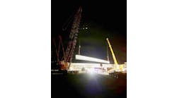
In many respects, the construction of the South Road Superway is being performed in the same manner as a traditional precast segmental balanced-cantilever bridge. Segments are joined to the existing structure in balanced pairs, and held permanently into place with post-tensioning tendons in the top slab. Once opposing cantilevers meet at mid-span, they are joined by a small closure pour, and secured with additional post-tensioning. The contractor is progressing on several fronts, and is using a variety of different equipment to erect the segments, including an erection gantry, smaller mobile lifters and ground-based cranes.
There are, however, several faces of the construction that are largely unique to Australia, which are discussed in greater detail below.
CFA is an abbreviation for “Continuous Flight Augur.” In this method, an augur with a hollow stem is screwed into the earth at the pile location. Once at depth, wet concrete is pumped under pressure down the hollow stem of the augur, as it is slowly withdrawn. The concrete backfills the void left by the rising augur, and since the hole is never empty, there is no need for a casing or drilling slurry. Once fully withdrawn, a prefabricated reinforcing cage is lowered into the wet concrete, and held in position while it cures. For this project, 1,050-mm piles were used, and they were installed to a depth of 24 m. The crews were generally able to install five piles per day.
The reinforcement used for all bridge construction in Australia is different than that used in the U.S. All reinforcement is grade 500 (i.e., 500 MPa, or approximately 75 ksi). It also is ductile and weldable. This last aspect is taken advantage of to a far greater degree than is common elsewhere. Welding is used as a working solution to reinforcement cage fabrication. Taken in conjunction with a complete ban on lap splices for shear reinforcement in the concrete cover, welded lap splices of reinforcement performed in the field are a frequent solution.
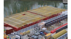
This ability has been put to work in a significant way in the fabrication of the precast segments. Australia has been at the forefront of the “slice” method of reinforcement fabrication. In this method, the transverse sets of reinforcement within a segment are prefabricated as a typical slice of the overall cage. The bars in each slice are laid out on a flat table with prepositioned guides, and tack-welded together. The typical slices are then hung up in storage until they are needed in a segment. The slices are quickly put into place within the mold, then tied together with small, straight longitudinal bars.
Up to speed
Major construction has been under way for nearly a year, and substantial progress has been made. All of the foundations and abutments have been constructed, and the 20th pier is nearing completion. Over 400 segments have been cast in the purpose-built casting yard. Segment erection is in full swing, and full or partial cantilevers have been erected on 11 piers to date. The project is expected to be complete in December 2013. R&B


