Thanks to the booming oil industry, the rapid growth of the economy in Equatorial Guinea has created a demand for expressways to develop a transportation system in the country.
The two cable-stayed bridges to cross the Wele River in Oyala were completed at the beginning of 2012. These signature bridges have become the emblematic entrance to the new city (Oyala) developed by the government of Equatorial Guinea. The bridges have been designed to have a clear identity without disturbing the natural environment. The minimization of material usage has been a major feat in order to reduce the construction cost due to difficult access to the site. The two bridges have similar characteristics. Both have an overall length of 492 ft.
Stay power
The design-build project was assigned by a consortium directed by Bouygues Bâtiment Guinée Equatoriale (BBGE), a subsidiary of the French firm Bouygues Bâtiment International, which carried out the construction of the two bridges. Pedelta was selected to design the bridges as well as to provide construction engineering services.
A balance between aesthetics and cost was a major concern in this signature project using transparent and slender forms. Two basic structure types were considered in the preliminary analysis: a concrete box girder bridge and a cable-stayed bridge, both using the balanced cantilever method. Other traditional bridge types, such as precast concrete I-beams or steel I-girders, were ruled out as they provide poor aesthetics. The cable-stayed solution was selected for its iconic value as required by the owner.
Due to the remote location of the two bridges, both the amount of materials and duration of construction had to be optimized. These bridges were conceived as a signature project where both structural form and relationship of the structure to the site were crucial in order to design bridges with a strong identity but without dominating the natural environment. The height of the pylons is lower than the surrounding trees.
Stay-cable-supported bridges have been used for more than 50 years and are capable of responding to a wide variety of spans. In these types of bridges, the deck is supported by the stay cables connected to a pylon, which usually has a height of approximately 25% of the main span. In the Oyala bridges, the impossibility of positioning the stay-cable anchorages of the deck in the middle of the cross section led to a solution with two planes of stay cables anchored on H-shaped pylons. Due to aesthetical reasons, the pylon legs open transversely toward the outside.
In the preliminary stages of the design, two solutions for the deck longitudinal beams were studied: prestressed concrete beams and steel I-girders. Both solutions proved to have a similar cost of execution, but the prestressed solution was chosen in the end because the materials were more accessible to the site.
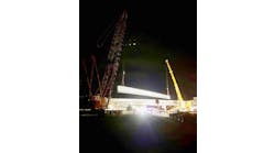
Construction of the central span was carried out using the cantilever method to reduce the construction’s environmental impact on the river.
From end to end
Each bridge consists of a continuous three-span structure with an 262-ft main span. The deck is only supported at the pylons and at the abutments. The length of the bridge provides a 135-m-wide hydraulic channel.
The cable stays are arranged in a semiharp configuration with backstays anchored at the end of the deck. The deck is vertically and transversely supported at the abutments and transversely supported at the pylons. Elastomeric bearings are used in all supports.
The deck, 74 ft wide, accommodates four traffic lanes, a central median and two pedestrian walkways. The deck is a composite steel-concrete structure supported by two lateral cable planes. It consists of two longitudinal depth cast-in-place post-tensioned concrete edge girders (grade fc=40 MPa). The longitudinal girders are 4.6 ft deep and the ratio depth-to-span length is 1-to-96. The longitudinal edge girders are cable supported by stays spaced at 22 ft apart, with 56-ft-long floor beams spanning the edge girders at 11-ft intervals.
All the stay cables are high-strength, multistrand cables (tensile strength of 1,860 MPa) with a maximum size of 19 strands (150 sq mm). The strands are galvanized and protected by an individual layer of high-density polyethylene (HDPE) and grease between the wires. The stay cables incorporate an outer HDPE sheath with double helical ribs to prevent rain- or wind-induced vibrations. Stays are anchored under the deck overhangs.
For cantilever erection, only two post-tensioning 56-mm-diam. bars (tensile strength of 1,060 MPa) per segment have been used to counteract the bending effect from the self weight of the cantilever and form traveler under construction. Each bar has the length of the segment and is connected to the adjacent ones by connectors. It was possible to use such a small amount of post-tensioning steel for the construction due to the exceptionally light form traveler used (16 tons per unit for a typical segment weighing 50 tons).
The permanent post-tensioning is composed of the 19 0.6-in. strands (150 sq mm), which allowed having just one type of stressing unit on-site to minimize the use of heavy stressing equipment. After the closure segment was executed, post-tensioning tendons were stressed using anchorage windows located in the top part of the deck. To avoid interference with the reinforcement of the cross section, rings were used on the anchor heads to stress the cables from the outside of the section.
Along the whole deck, I-shaped galvanized steel floor beams, spaced at 11 ft, support the slab. These beams have a variable depth between 33 in. and 41 in. and are connected to the edge longitudinal girders. The slab has a total thickness of 10 in. and includes 3-in.-thick precast concrete deck slabs.
The two stay-cable planes are connected to four pylon legs, forming an H-shaped pylon with open legs at the top. Each mast has a total height of approximately 89 ft, with 69 ft above the deck. The two masts of each pylon are connected by three cross beams: a steel tube on the top, a post-tensioned concrete beam under the deck level and a reinforced concrete beam at the foundation level (pile cap level).
The pylon legs have a solid reinforced concrete section until the first stay anchor and then the cross section is hollow, with an internal steel cage that provides anchoring for the stay cables. The cross section resembles a rectangle of 7×6 ft, and the wall thickness in the hollow part is 12 in.
One of the most exacting elements of the bridge is the abutments. The deck creates a downward vertical reaction when the back spans are built, whereas back stays transfer uplift reactions in service or in some stages of the balanced cantilever erection. Two inverted U-shaped concrete frames linked by a post-tensioned concrete cross beam are connected to the edge deck beams. Transfer of both downward and uplift forces is done through elastomeric bearings.
For the abutment, other alternatives were studied, such as anchoring the deck to the abutment footing with post-tensioning units, but this solution was discarded to avoid fatigue problems in the cables due to longitudinal movements of the bridge.
Behind the abutment, a system of retained earth was defined, which produces no pressure on the abutment walls and reduces the design shear force to be assumed by the foundations. This allowed the use of very thin concrete walls on the abutment and reduced the foundations of these elements.
Other specific elements are the elastomeric bearings located at the pylons. These elements, which were specially designed, allow vertical movements of the deck while serving as energy dissipaters for horizontal forces, necessary due to the seismic activity affecting the design. These devices are positioned on the pylon’s intermediate cross beam. To allow vertical displacements, the upper plate, which is connected to the deck longitudinal beams, has rings, and through these rings pass the rods which are connected to the elastomeric bearing.
A model move
For the structural analysis of each bridge, a global structural model was built using the software RMBridge v8i, which is specialized in advanced bridge analysis. The model encompassed substructure and superstructure components, including the counteracting uplift system at the abutment. All erection phases were modeled and adjusted in real-time during construction to take into account the actual duration of the stages, which influence concrete time-dependent effects, and changes that occur during the construction. Bridge design is an iterative process that interacts with construction. The parametric nature of the model allowed rapid response to the various alternatives and changes common in a project of this nature. The time-dependent concrete effects and changes in the structural model, soil-structure interaction, forces at the stays and other modifications during construction were accounted for.
The 3-D model uses a step-by-step integration in time. A parallel 3-D model for the global structure with shell elements was carried out in order to refine the grillage model concerning transverse behavior and effective widths of the longitudinal elements. For the local analysis of transverse bending, other separate finite-element models were developed to study local effects in the linear and elastic domain.
The foundations were analyzed with a 3-D FE global computer model to account for soil-structure interaction and examine more closely the distribution of internal forces and reactions.
The design of the internal deck top post-tensioning is governed by bending during construction, whereas the permanent tendons are designed to account for live loads and time-dependent concrete effects in service.
Stay-cable bridges allow stresses in the stay cables of up to 45% of the tensile strength for service limit states (SLS) and up to 67% for ultimate limit states (ULS). Additionally, the variation of stresses due to the fatigue live load is limited to 70 MPa.
Stay-cable forces were determined for permanent condition to minimize the bending moments in the deck and tower as well as deflections. The design of the stays was governed by the stress limitations in SLS and ULS. Verifications of fatigue, as well as stress limitations in construction, were verified. Additionally, accidental situations—like one cable replacement and the rupture of another cable—were investigated. The load of the sudden rupture of one cable was increased by a coefficient of 2.0 to take into account the dynamic effects arising from the impact. This is a value suggested in the CIP recommendations as well as in the Eurocode. This situation was considered together with 50% of the design traffic load acting on the bridge. Also, in accordance with the CIP recommendations, an overheating of 25°C in the stays was considered.
The seismicity of the area is moderate, with ground peak acceleration of ac=0.091g (g=acceleration of gravity).
Under, and over, construction
The construction of both bridges began in April 2010 and was completed in January 2012.
The foundations of pylons and abutments were done using footings on micropiles. The number of micropiles was minimized by inclining some of them. The length of the micropiles varies between 50 ft and 75 ft. The pylons were executed using a climbing formwork. Each jump was 19 ft long.
At the same time, the construction of the abutments was carried out. At these stages the deck was supported by temporary bearings at the abutment to take the downward force, which was basically the self weight of the abutment and a partial part of the side spans. The construction of the central span reduced the downward force until an upward force began to appear at the abutment. At this point the temporary bearings were removed and the uplifting system took the vertical uplift force. The first 117 ft of each side span was executed on falsework that was founded on an artificial peninsula.
The decks of the two bridges were erected using the cast-in-place segmental construction technology, taking advantage of cost-effectiveness, minimum disturbance to the river, accelerated construction time, aesthetics, use of local labor and materials, high quality control during construction that ensured excellent structural performance and safety, and durability.
First, the concrete of the longitudinal beams on falsework was poured, with the steel floor beams already positioned and the post-tensioning applied.
Before proceeding to the pouring of the concrete slab, the falsework was removed, leaving only a temporary vertical support located close to the pylon. This remained until the end of construction. The concrete slab of this part of the bridge was poured in two stages. In the first stage, two strips of the slab each with a 14 ft width, located at the junction with the longitudinal beams, were poured. In the second stage the 28-ft central strip was poured.
Once this step was concluded, the construction of the deck followed, using the cantilever method. Simultaneously, four form travelers were used on the two bridges. First, the cantilevers of both the longitudinal beams on the right side of the river of both bridges were executed. Afterward, the form travelers were transported onto the other side to proceed with the left-side cantilevers.
The form travelers were suspended underneath the longitudinal beams, and the segment length was 22 ft. The closure segment was poured at night to prevent tensile stresses arising in the fresh concrete due to thermal and shrinkage effects. To prevent the closure joints opening or cracking as the cantilever deflects, a small amount of post-tensioning was applied as soon as a resistance of 10 MPa in the concrete was reached.
Once the deck was finished, the permanent post-tensioning was completely applied and the barriers and pavement executed.
During the entire bridge construction process, the calculations were continuously updated to take into account actual site measurements of material properties as well as duration of the erection stages.
Counter deflections (camber) were applied to obtain during service lifetime the theoretical bridge axis. These counter deflections were calculated and applied to the deck longitudinal beams, steel transverse beams, pylons and pylon cross beams. Additionally, counter rotations were given to the stay-cable guide pipes to correct the rotations occurring during concrete pouring, stay-cable catenary and form-traveler deformability.
At the end of the construction, lift-offs were done on some of the stay cables to verify the actual cable forces. The technology used for both post-tensioned tendons and stays was provided by VSL. R&B