Test pilots speak of "pushing the envelope" when they test a new airplane. That pretty well describes what engineers from the Tennessee Department of Transportation (TennDOT) did when they designed and built the new bridge that carries Route 50 over Happy Hollow Creek in Hickman County.
The bridge, at 1,175 ft, holds the record as the longest totally jointless integral abutment precast concrete bridge to be built in the U.S. It features a composite concrete deck supported by 72-in. Bulb-T concrete girders.
Designed as a simple span for dead loads of beam and slab, it’s continuous for live loads and composite dead loads. What gives the bridge its unique character is the fact that it has no expansion bearings and no roadway expansion joints, according to Edward P. Wasserman, civil engineering director for TennDOT’s Division of Structures.
"It’s been our policy to design all bridges as continuous and jointless whenever possible," Wasserman said. However, that does not apply to bridges the length of the Happy Hollow Creek structure. "For concrete bridges up to 800 ft in length, we would go with a jointless structure without question. When we looked at this bridge, we questioned whether it was practical to extend beyond that length."
After much discussion, Wasserman said, TennDOT engineers calculated that the bridge could be designed in this fashion. It offered a clear opportunity to test the efficacy of designing and building a bridge this long with integral abutments and without joints, he added.
It’s integral
As engineers designed the bridge, they determined that the structure would tend to bow or bend laterally along the curved axis. Working with researchers at the University of Tennessee in Knoxville, the engineers calculated that movement well beyond the normally accepted 2-in. maximum range were possible. Movements of well beyond 4 in. in one direction were, in fact, acceptable according to university engineers. Having received that assurance, Wasserman said it was determined that the Happy Hollow Creek bridge would serve well as a test case. The decision came to make the bridge totally integral in construction.
The advantages of designing a bridge in this manner are many, according to Wasserman.
"First, it significantly reduces the cost of building the bridge," said Wasserman. "The elimination of all expansion bearings and all expansion joints provides a definite cost savings in construction."
A second major factor is speed of construction.
"Because we have no expansion joints and bearings in the structure, there are no shop drawings to review and no supplier of those components to deal with," Wasserman explained.
A third major advantage to building a bridge in this manner is that it provides a much stronger abutment system.
"It provides a much better distribution of wheel loads coming onto the bridge. Furthermore, the structure provides a much greater amount of redundancy in the event of some catastrophic occurrence. Although we are not in a seismic zone here, it is always comforting to know that we don’t have to be concerned with beams being shaken off the structure."
Perhaps as big a factor as any is that the structure requires virtually no maintenance.
"There is definitely less to maintain and that gives us the prospect of improved life cycle cost," Wasserman said. "For example, there is no penetration of water and salt into expansion joints, thus no corrosion and deterioration with which to be concerned."
The bridge, a graceful 4û curving structure, is super-elevated as it transitions into a spiral curve. It consists of nine precast, prestressed Bulb-T spans. The continuous superstructure is composed of chorded beams varying from 127 ft, 5 in. to 138 ft, 4 in. in length. The beams support an 8 1/4-inch-thick, 45-ft-wide concrete deck. The superstructure rests atop two post bents that vary in height from 51 to 91 ft. The superstructure is pin-connected to the bent caps and rests on ordinary 60-durometer neoprene pads.
The only accommodation to bridge movement from thermal expansion is at the end of the 25-ft approach pavements where an elastomeric concrete-silicon sealing joint protects the approach roadway pavement. To provide continuity in the bridge structure, a common diaphragm joins both ends of the girders in adjacent spans and the cast-in-place slab.
Two different precasters provided the components for the history-making bridge. The longest beams, 138 ft, 4 in. in length with 8-in. webs, came from CPI Concrete Products Inc., Memphis, Tenn. That firm cast six of the 72-in.-tall beams for the bridge’s longest span, and also provided 25,000 sq ft of precast, prestressed concrete deck panels. Standard Concrete Products Inc., Columbus, Ga., provided the 48 remaining 72-in.-tall, 6-in. webbed Bulb-T girders.
TennDOT engineers designed the bridge. Engineering on the precast concrete Bulb-Ts and deck panels came from CPI Concrete Products. In addition to casting most of the components, CPI also contributed its transportation knowledge to the project.
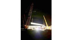
McKinnon Bridge Co., Franklin, Tenn., served as bridge contractor with Vaughn Contractors Inc., Waverly, Tenn., acting as general contractor. Setting the bridge required the use of two cranes, according to Mike McKinnon, president of McKinnon Bridge. "The location of the bridge and its limited access provided us with an interesting challenge," McKinnon said.
The challenge was overcome using two large cranes—one with 250-ton capacity, the other a 140-ton model.
Setting the scene
The cranes were assembled on the floor of the valley from where they would pick the various components and swing them into place on the bridge structure. The steep bluffs on either side of the river dictated that a launching truss be employed to maneuver the girders into position. The truss rolled the girders out to a position where they could be plucked from either end and swung into place atop the piers.
"The bridge was somewhat of a departure for us," said McKinnon. "Most often, we are setting bridges from barges in deep water. This time, we were working from dry land. The challenge here was that we were in a fairly deep gorge and setting the girders at heights of 90 to 100 ft. To be cautious, we actually used a little bit bigger equipment than we would normally have employed for components of this size."
McKinnon also pointed to the wintry weather during the construction of the bridge.
"We were working in snowy conditions much of the time. Even so, we were able to complete setting of the bridge in about two months time."
McKinnon lauded the manufacturers of the concrete components.
"The complicated geometry of the bridge could have proven a problem. We were working with a pretty sharp curve and the super elevation could have made fitting components in place a real challenge. The panel producer is to be commended for the accuracy of the shop drawings. As a result of their care, we encountered no particular problems on site."
The erection sequence for the bridge was carefully controlled by TennDOT policy. That policy requires one of several options employed by the contractor. He may either choose to pour the entire deck in one operation, concurrently pouring the diaphragm at the ends of the girders. If this is impossible, policy requires that no construction joint be located closer than 10 ft nor further than 15 ft from an interior support. Also, no diaphragm at an interior support may be poured unless the slab in the positive movement area of adjacent spans have been poured. These precautions prevent cracking of the common diaphragms at the supports.
Due to the length of the bridge, the second method was used at Happy Hollow Creek. To steady the beams during the interim, permanent intermediate diaphragms, composed of galvanized steel angles in an X-brace configuration, were placed at one-third points in each span near supports. Pouring sequences required that portions of the slab be poured concurrently with the abutment back wall and wing walls. This achieves the desired jointless deck with integral abutments. Although TennDOT permits removal of the galvanized X-braces near supports after the deck is poured, the braces were left in place in the Happy Hollow job.
"This is not unusual," said Wasserman. "It is generally easier to leave them in place than to take the trouble of removing them."
The bonus here is that leaving the X-braces in place just adds further strength to the bridge structure.
That’s the spirit
The bridge’s unique construction earned for its designers at TennDOT the prestigious 1999 Harry H. Edwards Award for Industry Advancement presented by the Precast/Prestressed Concrete Institute. The award goes to projects that advance the spirit of innovation in the precast concrete industry, using the material in unique and creative ways. The award particularly cites projects that demonstrate methods from which other designers can benefit by incorporating them into their own designs.
In presenting the award to the Happy Hollow Creek Bridge, the judges commented, "We applaud the state of Tennessee Department of Transportation for continuing to push the boundaries of this technology. They are sharply increasing the life cycle and decreasing the maintenance needs for bridge structures. This philosophy could be applied to other building types . . . applying this technology to a curved bridge in a very attractive setting adds to its appeal."


