Under self weight, the top and bottom chords of a truss bridge may be visualized as the bow and bow string of a bow-and-arrow set.
So what do you do if you must replace within a truss bridge all of the tension members, including all bottom chord members and pins, i.e., the bow string?
Most commonly, you would relocate the existing truss bridge to a staging area where a uniform support condition could be provided; or, as in the case of the Stonycreek River Bridge, you could look for a solution of “tension retention.”
Precarious prefatory
Built into an Appalachian Plateau river valley in the 1800s, Johnstown, Pa., flooded about once a year.
By the morning of May 31, 1889, water filled the streets and residents waited out the deluge as they had so frequently in the past. By late morning the prestigious South Fork Fish and Hunt Club’s earthen dam strained to hold back Lake Conemaugh, the club’s man-made pleasure lake, as men feverishly worked to prevent the dam’s failure.
Just past 3 p.m. the dam gave way and a 40-ft high, half-mile-wide thunderous wave of water and debris rolled into Johnstown claiming everything and everyone on its 14-mile journey.
After the deluge, the Stonycreek River Bridge and the adjoining inclined plane were subsequently built as means of “escape” should future dam breaks or severe flooding be imminent.
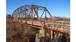
The Stonycreek River Bridge is a single-span, pin-connected, Pennsylvania Petit truss spanning the Stonycreek River in Johnstown, Cambria County, Pa. Originally built by the Cambria Iron Co., a predecessor of the Bethlehem Steel Co., in 1890, the bridge spans 230 ft and provides the singular means of access to the lower end of the world’s steepest vehicular inclined plane. Built as a lifesaver for the residents of flood-prone Johnstown, the bridge and the inclined plane, to which it leads, were built in response to the South Fork Dam break of 1889 and the resulting flood claiming more than 2,200 lives. Built of a trussed configuration, the Stonycreek River Bridge represents traditional 19th century craftsmanship. In this era, truss bridges were commonly built to span longer distances for reasons including smaller, more manageable pieces and a lower labor-to-material cost ratio.
Today, the Stonycreek River Bridge is listed on the Historic American Engineering Record (HAER) and the Inclined Plane, to which it leads, is listed on the National Register of Historic Places.
Rehabilitation resolve
Over the years, the bridge had experienced significant deterioration resulting in significant section and strength losses, prompting the owner, the Cambria County Transit Authority (CCTA), and the Pennsylvania Department of Transportation (PennDOT) to limit the vehicular weight permitted across the bridge. Analysis of the bridge revealed substandard capacity ratings for the trusses, floorbeams and stringers. Given the historic significance of the bridge, the CCTA and PennDOT elected to rehabilitate the bridge. As such, the selected rehabilitation design addressed these deficiencies by instructing the replacement of all tension members, pins, bearings, floorbeams, stringers and decking as well as all portal and sway bracing, in kind.
Dodging deformity
Fearing uncontrolled distortion of the structure if lifted and relocated to a work area per the rehabilitation bidding documents, the general contractor, Mekis Construction Corp., and the steel subcontractor, Alvarez Inc., sought independent engineering advice to determine if an alternative to the contract requirements was possible.
A concept for an auxiliary in-place post-tensioning (P/T) system was subsequently developed and submitted as a value-engineering (VE) proposal. This VE system proposal would effectively replace the function of the existing truss mechanics in much the same way as the function of the string on a bow is nullified during replacement. As such, relocation of the bridge for rehabilitation would not be required. Fundamentally the concept was very basic. As in a parallel circuit, high-strength threadbars would be positioned and tensioned immediately adjacent to selected primary members. Then the selected primary members, as well as connecting pins, would be systematically cut and replaced. Effectively this was a concept of “tension retention” with the temporary parallel members carrying the primary tensile member load. The proposal was quickly embraced by Mekis, Alvarez and the owning agencies.
Systemic simplicity
The VE system utilized the application of post-tensioning at five locations. Post-tensioning was applied at the bottom chord and at web primary diagonal tension members.
Application of post-tensioning forces at these locations resulted in a static mechanism by which all existing members for replacement were accessible and could be removed.
Upon P/T force application, the elegance of the VE hybrid system may be visualized as follows. Under dead loading, the VE system completely removed all tensile forces from the truss tension members. Subsequently, the truss tension members and connecting pins could be removed and replaced.
Under dead loading the concept is no more complex than changing the string on the bow of your bow-and-arrow set as a child; to change the string simply push the ends of the bow together until the string is no longer tensioned, then remove and replace.
Under combined dead and live (crane) loading conditions, the VE system transferred force around missing elements by combining the structural capabilities of the VE system and the remaining engaged truss members to maintain stability and to limit displacements. Under combined dead and live load, the VE system operated on the premise that the function of a series of small, triangulated members can be replaced by a larger system of triangulated members. In terms of application, as segments of the smaller existing triangulated truss system are temporarily removed, the triangulated exo-system functioned as the primary load-transfer mechanism, passing force by “open-truss”/arch action around the “hole” in the smaller existing system.
The VE system permitted in-place truss rehabilitation without requiring bridge relocation or temporary support towers.
The concept of applying post-tensioning to facilitate rehabilitation has been well documented through engineering history. John Roebling, in one of his first projects, effectively applied post-tensioning to strengthen the Allegheny River crossing of the Pennsylvania Canal in Pittsburgh. Likewise, the ability to pass system forces around missing elements or holes in a structure is not new and has been witnessed in the past. However, the notion of implementing this type of systemic post-tensioning, as in the case of the VE hybrid system, is rarely considered because of the inherent lack of system redundancy and the limited precautionary fail-safe measures that can be employed.
Post-tensioning particulars
To accomplish the required post-tensioning, post-tensioning anchorages were designed and utilized. To eliminate eccentric load effects at the joints, post-tensioning threadbars were positioned as closely as possible to the working centerline of the pins. This intent to eliminate eccentric effects, however, dictated the post-tensioning threadbars be positioned laterally such that the existing pins could be removed and replaced with the new pins.
To reduce demand on the post-tensioning exo-system, loading on the bridge structure needed to be reduced. Therefore, the weight of the ticket house on the west end of the bridge was temporarily removed by blocking the ticket house rear support beam on the abutment and supporting the ticket house front support beam on temporary towers. Additionally, to reduce the overall bridge weight, the out-to-out deck width was reduced by 10 ft (5 ft per side).
Bridge rehabilitation operations were configured such that work progressed from the ticket house end to the vehicular approach ramp end of the bridge (west to east) and sequenced such that all new members were installed prior to advancing to the next bay. This eliminated the need to provide access to areas from which rehabilitation had progressed. This also permitted use of a 25-ton rough-terrain crane for existing member removal and new member delivery to all locations as sequenced. While utilization of the crane resulted in almost the complete elimination of member delivery via chain-falls, it also meant that the post-tensioning exo-system would need to carry the crane loading.
Using the in-depth inspection notes taken and analyses performed on the bridge by the rehabilitation designer, structural models of the existing bridge with the post-tensioned exo-system were developed for every step of the sequenced rehabilitation. Baseline models were developed to determine required post-tensioning forces. Subsequent sequence models were developed to determine connected member stresses throughout rehabilitation and expected structure displacements, as well as verify stability.
It is important to note that for this type of system the prescribed post-tensioning force to be applied must precisely balance the dead loading of the bridge. Required post-tensioning forces for the system are a function only of structure geometry and self-weight. While a self-weight estimate can be used to determine approximate post-tensioning forces, it is critical that the actual weight of the bridge be determined and post-tensioning forces adjusted accordingly prior to severing the first existing member. Since the pin-connected bearings for the Stonycreek River Bridge were to be removed and replaced, a jacking/temporary support system was designed permitting structure jacking for bearing replacement and weighing of the bridge. This provided an accurate assessment of the bridge weight for determining final post-tensioning force requirements.
Due to the top chord not being configured to the shape of the theoretical pressure line for a condition of dead loading, strengthening at kinked-joint intersections was required to accommodate the post-tensioning forces.
In terms of structural displacement of the truss during rehabilitation, contrary to the conventional wisdom that worst-case displacements occur at the middle of the span, modeling revealed that maximum displacement would occur at the first inboard panel point during rehabilitation of the first bay. Therefore, the most critical period of the rehabilitation occurred at the beginning of rehabilitation.
Truss tension member replacement requires significant forethought and effort. Rehabilitation of the Stonycreek River Bridge in Johnstown with this VE system demonstrated that application of the “tension retention” concept can be an effective alternative to the traditional truss rehabilitation practice of bridge relocation to uniform support.


