Long-span suspension bridges with spans over 2,300 ft have not been built in the U.S. for the past 36 years when the 4,260-ft main span Verrazano Narrows bridge opened to traffic in 1964. In 2004, the Carquinez Bridge, with a main span of 2,388 ft, will be ready for action. It will be the first orthotropic steel box girder suspension bridge ever built in the country.
The bridge, which spans the Carquinez strait about 20 miles northeast of San Francisco, is located within a few miles of several active faults. While other famous suspension bridges like the Golden Gate Bridge and the San Francisco-Oakland Bay Bridge are undergoing major seismic retrofit, Carquinez Bridge is the first bridge in the U.S., located in a potentially high seismic risk area, to be designed to present-day stringent seismic design standards.
The first Carquinez bridge, designed by David Steinman and Charles Derleth, was built in 1927 by the American Toll Bridge Co. It replaced a heavily used ferry service and cleared a bottleneck on the highway between San Francisco and Sacramento. The state of California acquired the bridge in 1941 and in the face of growing traffic needs designed and constructed a second Carquinez Bridge in 1958. Completion of the second bridge was part of an ambitious project that transformed a two-lane road into the modern eight-lane interstate highway of today. Both bridges are multi-span cantilever truss bridges with maximum spans of about 1,180 ft.
Considering the potential for seismic activity in the Carquinez strait, safety initiatives prompted the California Department of Transportation (Caltrans) to commission retrofit studies of the existing structures. These studies were carried out by a joint venture team of HNTB, Oakland, and CH2M Hill, Oakland. As a result of these studies, replacement over retrofit was considered the best “overall value” for the 1927 bridge due to several reasons: the bridge had severe seismic deficiencies; its main members required rehabilitation due to fatigue and corrosion; the concrete deck required replacement; and the lane width were substandard with no shoulders. The state chose to replace the 1927 bridge, and the 1958 bridge was considered for seismic retrofit for continued service.
Caltrans chose the joint venture team of De Leuw, Cather & Co., San Francisco, Steinman Boynton Gronquist & Birdsall, New York, (both firms are now part of Parsons Transportation Group) and OPAC Consulting Engineers, San Francisco, to design the replacement bridge. A type selection study was undertaken by the consultants to choose between cable stayed and suspension bridge alternatives. The study concluded that a two-tower suspension bridge would cost about the same as a three-tower cable-stayed bridge. However, for reasons of better seismic performance, shorter construction schedule, better aesthetics and less construction risk, the suspension bridge alternative was chosen for final design.
Everything ties into the towers
The new Carquinez Bridge has a total length of 3,464 ft between the north anchorage and the transition pier. The bridge will carry four lanes of traffic along I-80 in addition to a pedestrian/bike lane. The overall width of the bridge deck between the main cables is 89.2 ft.
Towers: Two reinforced concrete towers of the bridge will rise about 410 ft above the water level. Each tower leg consists of a hollow box section with spirally reinforced corner pilasters about 3.3 ft in diam. connected by 19.7-in.-thick walls. This hollow cellular section was shown to provide superior seismic performance as well as agreeable aesthetics. The tower legs have been designed to behave elastically under the most severe design earthquake forces with limited inelasticity being permitted at the tower base. Two reinforced concrete struts connect the two tower legs. The struts have been designed to remain elastic. The strut nominal capacity is 20% greater than the plastic moment capacity of the tower legs. This design ensures that any inelasticity will occur in the more ductile tower leg rather than the post-tensioned struts. Tower legs at both the north and south towers are currently under construction using the jump form method of construction.
Tower piles: Each tower leg is supported on six 9.8-ft-diam. drilled shaft piles. Steel casings with an average length of about 155 ft for the south tower and about 127 ft for the north tower are driven to bedrock. The rock sockets are about 141 ft long at the south tower and about 79 ft long at the north tower. The piles are detailed to provide adequate ductility and confinement to withstand the large seismic forces.
Tower foundations posed one of the biggest construction challenges of the project. Construction of the north tower piles involved driving the casings to the specified tip. The casings were then cleaned out and an 8.9-ft-diam. rock socket was drilled beyond the tip of the casing. Polymer slurry with 6% salt concentration was used to stabilize the hole and to minimize softening and swelling of soft claystone and siltstone present in the rock. Once the rock socket tip elevation was reached, the rebar cage was lowered and concrete placed using a tremie pipe displacing the slurry. The rebar cage was then lowered in the casing and lapped with the rock socket cage. Concrete was then poured into the casing to complete the pile construction.
The rock mass at the south tower piles is highly fractured, and polymer slurry was not able to stabilize the rock socket hole. Thus, a different construction method was employed. Once the casing was in place, a 10.8-ft-diam. under-reamer was used to drill about 25-ft-deep segments, which were stabilized using polymer slurry. A lean concrete mix was then placed by tremie. Once the concrete hardened, an 8.9-ft-diam. hole was cored through the concrete ensuring a stable hole for the rock socket. Thus, proceeding in segments of about 25 ft, the rock socket tip was reached. Pile construction was then completed using the same procedure that was used at the north tower piles.
Tower foundations and footing forms: The tower foundations are about 7.6 ft below the mean sea level. To avoid construction of the footings under water, the designers envisioned the use of precast footing forms. These precast forms were supposed to be floated to the site and positioned in place at the exact location and elevation over an erection frame supported on temporary piles. The precast form would act as a cofferdam for the construction of the footing and also act as a template for driving the drilled shafts.
However, the contractor chose to modify this construction method. Since the construction of the drilled shafts was on the critical path, the contractor started the construction of the shafts sooner while the precast forms were still being fabricated. Once the drilled shafts were constructed and the footing forms fabricated, the forms were floated in place at high tide and lowered on top of the piles. The contractor used a positioning system for the drilled shafts that allowed tight tolerances on the horizontal position of the steel casings, which ensured proper mating of the precast footing forms to the casings.
This construction technique will now be used on two other San Francisco Bay-area bridges which use large diameter drilled shaft piles and footings which are below water: the new Benicia Martinez Bridge and the San Francisco-Oakland Bay Bridge east span replacement project.
Transition pier: The pier is located at the south end of the suspension bridge where it transitions to a steel girder supported span of the approach viaduct. The approach viaduct is designed by Caltrans and the real challenge in designing the structure was to mate the two bridges with vastly different dynamic response during an earthquake. The suspension bridge is much more flexible than the approach viaduct. Thus the steel box girder superstructure of the viaduct is designed as an isolation structure to accommodate up to 4.9 ft of differential movement longitudinally between the two bridges, providing a flexible link.
The pier column cross section is a hollow rectangular box with spirally tied corner pilasters. The bent cap supports the suspension bridge loads through tall rocker links and also loads from the approach viaduct girders. In keeping with the Caltrans seismic design philosophy, the pier is designed with a strong cap/weak column with plastic hinges forming at the column top and bottom in a transverse earthquake.
In addition to supporting loads from the bridge decks, the pier also supports cable tie-down loads. The tie-down sections pass through the hollow columns and are anchored into the footings. To prevent the tie-down forces from being transferred to the columns, tie-down anchor rods are grouted in the solid sections at the base of the columns and the cap only after the superstructure box girder is erected and its load transferred to the footing. Each column is supported on 25- to 30-in. cast-in-steel shell concrete (CISS) pile. Because of the high tensile load from the tie-down, the net compression force on the footing is considerably reduced.
Deck: The new Carquinez Bridge will be the first major suspension bridge in the U.S. to use a closed-steel orthotropic box girder deck. This design is particularly effective in resisting bending stresses because of the large flange area. At the same time the closed box shape provides adequate torsional rigidity against wind, seismic and other asymmetrical loads. In cross section, the box girder is 9.8 ft deep and 95.1 ft wide. The edge plate and side plates are shaped to provide an aerodynamically stable cross section.
The suspended superstructure is designed as a continuous element with expansion joints only at the extreme ends of the girder resulting in a total girder length of 3,464 ft. The box girder offers many advantages over truss-stiffened suspension spans including lower steel costs and lower maintenance costs, since much of the steel surface is sheltered within the section. The design of the deck incorporated several advances in fatigue endurance and innovative use of groove-welded connections. These innovative modifications were made and validated as part of full-size physical testing for the Williamsburg bridge deck replacement in New York City.
Longitudinal bulkheads are provided to improve the vertical shear carrying capacity of the box and to accommodate seismic demands resulting in large bending moments about the vertical axis of the girder. The bulkheads also act as longitudinal distributing members along the box girder between two transverse bulkheads. Transverse bulkhead spacing is determined by the spacing of the suspenders, which is 40.7 ft. Coincident with each suspender, a transverse bulkhead is provided with an intermediate bulkhead between each of them. A determining factor for spacing the transverse bulkheads is the maximum desirable span of the orthotropic deck. By maximizing the span of the orthotropic deck, the number of transverse bulkheads is reduced by more than 25%, as compared to the spacing of about 15 ft incorporated into several European and Japanese designs.
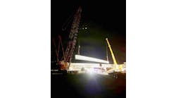
Initial fabrication of the bridge deck is being carried out by the Japanese firm Ishikawajima-Harima Heavy Industries Co. Ltd. at their plant in Japan. The fabricated box girder segments will be transported across the Pacific Ocean to the Carquinez bay and lifted directly onto the span in their final position.
Suspension system: Each main cable consists of 8,584 zinc-coated, carbon-steel wires compacted into a diameter of 20.2 in. The No. 6 gage cold drawn wire has a specified minimum ultimate strength of 228 ksi and a minimum yield strength by the 0.2% offset method of 170 ksi. A maximum allowable working stress of 100 ksi was used.
Following compaction of the main cable into its circular shape and prior to wrapping it with No. 9 gage galvanized steel wire, the cable will be coated with a high metallic zinc content polyurethane base waterproofing paste. This paste product was successfully used on the Storebealt Bridge in Denmark and has gained favor for several recently constructed suspension bridges in Norway. Placed to fill the interstices between the wrapping wire and the main cable wires, the paste will physically bond to the wire surfaces, providing a flexible and waterproof barrier. Over-coating the wrapping wire with a multi-coat system of highly elastic acrylic-polymer paint provides further waterproofing.
In the splay chambers of the gravity anchorages the main cables each splay into 37 individual strands, with each strand secured around strand shoes of conventional design. This design approach considers that the cables will be constructed by air spinning, which reflects the contractor’s selected method of cable erection. Each strand shoe is connected to a pair of anchor rods that extend to the rear of the gravity anchor block and attach to a series of steel anchor girders embedded in the concrete anchorage.
The suspenders are standard zinc-coated steel structural wire rope. For the manufacture of the suspender assemblies, resin socketing has been selected over the alternate zinc socketing for improved fatigue performance and corrosion prevention. The suspenders are connected to the box girder with external linkage assemblies providing a maintainable and inspectable system. All linkage components are hot-dip galvanized with stainless steel pins, making the entire assembly consistent with the specified 150-year design life. The short suspender assemblies near the expansion joints at the end of the side spans have been provided with low-friction spherical bearings to provide for multi-directional rotation of the socket attachments. Additionally, each link has a lug for the attachment of a jacking device to facilitate future suspender replacement.
Suspenders are designed with a safety factor of 4.0 against the ultimate breaking strength, including efficiency losses resulting from looping the ropes over the cable bands. A built-in redundancy is provided in the design by including a pair of suspender ropes at each connection point. The design also provides sufficient suspender capacity in the unlikely event of the loss of one suspender group.
Anchorages: The subsurface condition at the two cable anchorages is significantly different. As a result their geometry as well as their foundations are different.
North anchorage: This is a gravity-type anchorage, which is located high up on a rock buff overlooking the Carquinez strait. The anchorage is combined with the bridge abutment, which supports the bridge deck through tall rocker bearings. The underlying rocks are folded and fractured with the strike and dip varying across the site. Geologic mapping and subsurface exploration identified a series of shear zones and faults, though there was no evidence to suggest that these features were of tectonic origin. To reduce the pressure on the rock buff, the anchorage is located about 115 ft from the face.
The top of the buff will be benched to allow the bridge girder to span to the abutment. The heel of anchor blocks for each cable is embedded about 65 ft in the rock and rises in steps up to the abutment seat. Resistance to the large cable forces is provided by base friction as well as the passive resistance against the embedded structure. To enhance the resistance of the anchor blocks against block failure of the buff the two blocks are connected by a massive grade beam. This helps to mobilize a much larger block of rock mass providing increased factor of safety against failure.
South anchorage: Unlike the north anchorage, the south anchorage is located on fill underlain by soft clay, loose sand and weathered rock. With high ground water, the sand was found to be susceptible to liquefaction. The lateral resistance to the cable pull is thus provided by 380-30-in.-diam. CISS piles—171 of these piles are vertical and the rest are driven at a batter of 3:1, with the batter being in the direction of the cable pull. The cable splay chambers and part of the anchor blocks are above ground with the remaining anchor block embedded below grade. The anchorage is located well south of the transition pier and below the approach viaduct. Its location was partly determined by the presence of Union Pacific railroad tracks, which were to be cleared by the main cables.
Strong on all levels
The bridge is being designed for two levels of earthquake, the Safety Evaluation Earthquake (SEE) corresponding to a maximum credible event with a 1,000- to 2,000-year mean return period and the lower level Functional Evaluation Earthquake (FEE) with a 300-year mean return period. Under a SEE, any damage to the bridge has to be readily repairable without limiting traffic on the bridge. Under a more frequently occurring FEE the damage would not require repair or cause any permanent offsets. As much as possible, the Important Bridge criteria as required by Caltrans are met. Performance criteria are set by limiting strain levels in concrete, reinforcement and steel elements.
When designing for an FEE event a maximum concrete strain of .004 was used for reinforced concrete elements. For a SEE event, the stress-strain relationships proposed by Dr. J.B. Mander for confined concrete were used. For the tower piles, this strain was limited to 75% of the ultimate strains determined by Mander’s equations.
To achieve the performance goals under a FEE event, the tension reinforcement strain was limited to .015. Similar limits were established under the SEE event for ultimate strains as well as design level strains. Limiting strains in the steel casing of pile shafts also was established for pile compression as well as longitudinal and hoop tension.
Geomatrix Consultants, Oakland, carried out seismic ground motion study for maximum credible earthquakes (MCE) on the governing faults. Three design earthquakes were selected for the Carquinez Bridge.
Comparison of the response spectra of the MCE on the San Andreas, Hayward and Franklin faults indicate that the spectral values for the Franklin event are equal to or higher than the other two events over the entire period ranging from 0 to 7.5 seconds. The response spectrum for this event was selected as the design response spectrum. Three sets of multi-support rock motions based upon the Franklin event were developed for the non-linear time-history analysis of the bridge.
Rock motions were developed at each support location of the bridge corresponding to the SEE. Near-source effects were incorporated in these motions to account for directivity effects. Also included were spatial variation in the motions over the length of the bridge.
Modeling for research
The seismic performance evaluation of the bridge made use of a global inelastic dynamic computer model of the entire bridge. Seismic demands obtained from the structural analysis were compared with the capacities of the respective elements to ensure that their seismic performance is consistent with the project design criteria.
The global analysis was supported by detailed component analysis of the steel box girder deck, tower legs and tower piles. Local component analysis helped provide insight into their performance resulting in considerable design and detailing refinement.
Modeling: A global model of the bridge was developed from the north to the south anchorage. The model included the Crockett approach viaduct on the south side of the bridge, which was designed by Caltrans. The model captured the interaction between the approach viaduct and the suspension bridge.
The global model accurately represented the bridge geometry, stiffness and mass and considered all important structural components including pile foundations, anchorages, main towers, transition pier, cables, suspenders and the orthotropic deck. To start with, a linear elastic model was used, but this was refined during the analysis as geometric nonlinearity was introduced in the cables and material nonlinearity was introduced in concrete elements found to experience inelastic behavior.
In the time history analysis, which was based on the Newmark Implicit Integration method, Rayleigh damping was used for the structural elements with the damping matrix C=aM + bK. Here M is the mass matrix and K the stiffness matrix. The mass proportional damping a and the stiffness proportional damping b were determined for each element group by following an iterative process.
Minor inelastic deformations were permitted at the base of the tower leg and below the lower strut under extreme seismic loads. Moment-curvature (M-F) relationships were developed and used at these locations to model the material nonlinearity. Nonlinear M-F relationships also were used to model the material behavior over the full length of the piles. The M-F curves varied over the height of the piles with variation in reinforcement and confinement provided by the cap, the shell and the rock.
Additional hydrodynamic mass and soil mass is added to the pile elements through discrete lumped mass at the nodes. The hydrodynamic mass was assumed to be equal to the volume of water displaced by the piles. The soil mass tributary to the tower piles was assumed to be the volume of soil contained within a “doughnut” of a radius equal to 1.5 times the pile radius.
Analysis results: The nonlinear time history analysis of the bridge was performed using the ADINA program. Results obtained from this analysis were used to design the various bridge components.
The tower struts, which are post-tensioned boxes, have been designed to remain elastic during the SEE. The upper strut has been designed to have a flexural capacity 1.2 times the tower leg plastic moment capacity. This ensures inelastic deformations are limited to the legs. The lower strut has not utilized the same criteria, since designing the strut for combined plastic moments above and below the strut would be unrealistically conservative. The lower strut has been designed for a nominal moment of 1.2 times the elastic demands found from the global seismic analysis.
For the purpose of evaluation, the tower piles are assumed to have three distinct sections:
1) Pile at the pile cap where the rebar cage extends into the cap;
2) Pile below the cap and above the rock socket where it is confined by a permanent casing 13/4 in. thick. Casing contributes to both lateral confinement and flexural strength; and
3) Pile within the rock socket.
Pile flexural capacity was obtained from an M-F analysis for varying axial loads. The capacity was based either on the limiting compressive strains in the confined concrete or tensile strains in the reinforcement or the permanent casing. In determining the capacity of the pile section with casing, the shell thickness was reduced to account for corrosion.
The adequacy of the pile sections under seismic loads was determined by plotting the curvature capacity of each section at varying loads. Seismic curvature demands and the corresponding axial load on the pile at various time steps was plotted on this same graph. If the capacity curve enveloped the data points obtained from the seismic demands, the section design was assumed to be adequate.
Local modeling: Local structural models were developed to support seismic analysis and design. Models of the tower bases, piles and pile caps were developed to verify design capacities, section ductilities and evaluate compliance with the seismic performance criteria. This advanced analysis work was performed by Anatech Consulting Engineers, San Diego, and SCSolutions Inc., Santa Clara, Calif.
Local continuum analytical studies were performed for lower/upper strut-to-column joint region and for the tower base/pile-cap/pile system to verify this system’s seismic performance.
Ready to ride
The new Carquinez Bridge was designed for forces obtained using state-of-the-art analysis methods. Rock motions at each support were developed corresponding to the SEE incorporating the near-source effects. The three-dimensional model of the bridge incorporated geometric nonlinearity in the cables and material nonlinearity in the concrete elements which show inelastic behavior. Soil-structure interaction was considered using foundation impedance matrices.
Seismic studies demonstrated that the bridge design meets the seismic design criteria adopted for the project. During a SEE event, minimal damage is expected in the tower legs and tower piles, which could result in cover concrete spalling and limited yielding of the reinforcement. During a FEE event, no damage is expected to these bridge elements.
Suspension bridges are inherently flexible structures with the suspended superstructure and tall towers resulting in long periods of vibration. Thus, these bridges are well suited in areas of high seismicity. The new Carquinez Bridge should therefore ride out the next big earthquake without suffering major damage.