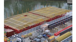
Constructed in 1963, the existing northbound Van Wyck Expressway (VWE) viaduct consists of steel-plate girders and rolled stringers in an 18-span configuration with an overall length of 1,329 ft. It carries two lanes of traffic over the Grand Central Parkway (GCP) corridor, Union Turnpike (UTP) and the Jackie Robinson Parkway (JRP) within the Kew Gardens Interchange (KGI). |
The bridge is being replaced as part of a New York State Department of Transportation (NYSDOT) interstate highway improvement to address existing highway operational and structural deficiencies in the KGI area of Queens, N.Y.
The replacement structure was designed to be fully jointless to eliminate typical deck joints, which are costly to maintain and are a main cause of superstructure and substructure deterioration. The four-span, continuous, steel-girder bridge replacement, at a length of approximately 800 ft, will be the longest fully jointless curved structure owned by NYSDOT when completed.
The project area, located in Region 11 of NYSDOT in New York City, includes several major highways. This area makes up what is known as the KGI. The roadways in the interchange handle a combined daily traffic volume of more than 520,000 vehicles per day. Due to the complexity of the interchange, the program is being progressed under three separate construction contracts.
Take them away
Significant bridge deterioration can occur at deck joints. Problems with deck joints can lead to the introduction of water, debris and deicing agents to the superstructure, bearings and substructure components at these locations, resulting in the premature deterioration of these bridge elements. The replacement costs of these elements and of the joint itself vary based upon the element types, span lengths and bridge location.
The northbound VWE design traffic volume is 98,000 vehicles per day with 10% truck traffic. It is directly north of the JFK Airport and is the main truck route from the airport bringing shipments into the region. Based on experience with similar roadways, NYSDOT has had maintenance concerns on similar structures that have used multicell modular joints. As such, NYSDOT requested that the structure be analyzed to determine if a jointless alternative was feasible.
The high traffic volume on the VWE bridge and on the at-grade roadways crossed by the bridge makes future repairs/replacements of these components and the joint itself a major concern. By eliminating all joints along the deck and at the abutments, these concerns can be addressed.
Additional measures also were employed to reduce the overall maintenance requirements for the northbound VWE viaduct to reduce life-cycle costs. These included reducing the overall length of the structure by extending the at-grade portions using fill-type retaining walls; the use of weathering steel; the use of elastomeric bearings; and the use of stainless steel reinforcement in the bridge deck.
Long and curve of it
The proposed viaduct will be a four-span, continuous, steel-plate girder, with span lengths of 192 ft, 213 ft, 213 ft and 179 ft for an overall length of approximately 800 ft. The vertical profile has a crest curve along with horizontal compound curvature with approximate radii of 2,000 and 3,000 ft. The substructure consists of concrete piers supported on piles. Elastomeric bearings are used with expansion provided at Piers 1, 3 and at the abutments, with fixity provided at Pier 2. To provide superstructure guiding, concrete shear blocks with steel guides at the piers and abutments are included. The proposed structure will have improved highway geometry and carry three lanes of northbound VWE traffic in the future.
Several existing jointless options typically used by NYSDOT were reviewed. These included integral abutments, semi-integral abutments and jointless-deck details. The proposed structure length of 800 ft, expansion length of 405 ft and curvature of the structure made the integral and semi-integral options unfeasible. Based on NYSDOT criteria for semi-integral and integral abutments, the allowed maximum expansion length of 165 ft and maximum curvature criteria were exceeded. The existing jointless-deck details used by NYSDOT are applicable to structures that meet the criteria of expansion lengths up to 200 ft with less curvature than the proposed northbound VWE. Based on the limitations of the existing criteria for these options, additional analysis and development were required for the range of thermal movements to be experienced by the structure.
A finite-element model (FEM) of the superstructure was developed to analyze the structure movements through the full thermal range based on AASHTO LRFD. This FEM included all primary members of the curved structure.
A uniform application for the full temperature range of 0°F to 120°F was applied to the structure assuming a base construction temperature of 68°F. To model the effects of a nonuniform temperature distribution on the structure, a temperature gradient of 20°F was applied from one fascia of the structure.
Additional model assumptions are outlined as follows. Temperature ranges used were based on AASHTO LRFD 4th Edition, Table 3.12.2.1-1 and applicable blue pages for NYSDOT Region 11. The structure displacements were computed along and perpendicular to the theoretical chord line of the structure between Pier 2 and the abutments. The cross slope and longitudinal slope of the structure were considered but were not included in the FEM. The modeling of the interface points between the structural slab and its supports within the approach were based on an average coefficient of friction for the bond-breaker pad material (0.2) and for concrete to concrete (0.6) per ACI Code.
The thermal-modeling analysis demonstrated the longitudinal and transverse range of thermal movements that the structure would expect to see in service. Under uniform temperature application, the predominant movement is in the longitudinal direction as anticipated. With the uniform temperature application, the horizontal curvature of the structure introduces transverse displacements which need to be accounted for in the jointless design. When the nonuniform gradient temperature is applied to the fascia of the structure, additional transverse displacements are exhibited.
The results of the analysis found the maximum longitudinal displacement range to be 3.75 in., while the maximum range for transverse movements was 1.32 in. The jointless details were developed to allow for these movements.
Joint-less details
The final structure configuration eliminates all deck joints on the bridge and at the abutments. Allowing for the longitudinal and transverse thermal movements with minimal friction between the contact points of the structure and approach supports to avoid binding and associated forces was an emphasis in design. To achieve this, the deck slab was continued over the back wall and is supported upon longitudinal grade beams within the approach. The deck-slab extension becomes the approach slab.
The longitudinal grade-beam supports reduce the area of contact between the approach slab and this interface. This smaller contact area also will allow better control on the construction tolerances of these interface points. To reduce frictional forces between the approach slab and longitudinal grade-beam supports, the grade beams will receive a steel-trowel finish with final top surfaces set to match the profile and cross slope of the roadway. A two-layer synthetic bond-breaker material will be installed between the top of the grade beams and the underside of the approach slab to reduce friction at this interface point.
Beyond the approach slab is an asphalt pressure-relief joint supplied to handle the longitudinal movements. This pressure-relief joint is supported on a sleeper slab that also is supported upon the longitudinal grade beams within the approach.
The subgrade below the grade beams will consist of a select structural fill compacted to 95% standard proctor. This is provided to address potential settlement at the approach grade beams, while weep holes and underdrains at the sleeper slab below the pressure-relief joint have been provided to address potential water.
To reduce friction and binding, a 1-in. gap between the top of the back wall and the underside of the deck slab/approach slab was provided at this location. This gap is filled with compressible foam. To address potential friction under the approach slab, the underside of the approach slab receives a 6-in.-deep haunch between grade-beam supports to provide a gap between the underside of the slab and the approach area select structural fill.
The transverse movement of the approach slab at the wing walls was addressed by casting the slab above the wing walls. A gap between the top of the wing wall and the underside of the approach slab is provided and filled with a bond breaker so as not to restrict the transverse deformations at this location.
Although no movement is anticipated at the sleeper slab to wing wall location, a 2-in. transverse gap with compressible filler is supplied to alleviate potential stresses between the sleeper slab and wing walls if future movement of the sleeper slab does occur.
Additional reinforcement at the deck and abutment areas was provided to handle potential forces that may potentially be transmitted back through the jointless system. The structure was checked to ensure potential forces generated by a failure of the joint could be handled by the sub- and superstructure.
For future use?
In an effort to reduce maintenance of the proposed northbound VWE viaduct in the KGI area, NYSDOT will utilize the proposed details to eliminate all joints on the structure. The details are being implemented as a pilot program by NYSDOT to determine their effectiveness. The typical jointless details used by NYSDOT have been limited to shorter, less curved bridges with expansion lengths of only up to 200 ft. The proposed 800-ft-long northbound VWE bridge is curved and has an expansion length of 405 ft, which will make it the longest curved structure to be fully jointless in NYSDOT’s inventory. The developed details have the potential to greatly minimize deterioration of the structure and reduce the maintenance and associated life-cycle costs. Although the pressure-relief joint will itself require maintenance, the DOT views this as minor, routine maintenance compared with a replacement of a failed multicell modular for this high-traffic structure. The project is currently in construction, with the bridge to be in service by 2015.
Thermal modeling of the curved structure revealed that transverse movements from uniform temperature application could be significant and need to be considered in joint design. The application of the nonuniform thermal gradient on the curved structure was shown to add to the overall transverse displacement, warranting consideration in joint design. As a pilot program, the tracking of the in-use results of the joint, its durability, effectiveness and the required maintenance cycles of the pressure-relief joint will be compiled and reviewed. This data will allow NYSDOT to determine if implementing more jointless details on longer span and curved structures is feasible. R&B


