In January 2011, the Memorial Bridge connecting Portsmouth, N.H., and Kittery, Maine, was permanently closed after 88 years of service.
Although anticipated, the closure severely disrupted lives on both banks, given the interconnectedness of these two communities. It had allowed residents to live on one side of the river and work, shop and play on the other side. What’s more, it was the area’s only pedestrian and bicycle crossing, resulting in a detour of more than 20 minutes outside the project area.
Carrying U.S. Highway 1 over the Piscataqua River, this vertical-lift bridge accommodates 12,000 vehicles a day and more than 1,500 residents traversed it—many of whom do not own a vehicle because the bridge put everything they needed within walking distance. Closing the bridge meant leaving many of those residents with no way to access the opposite side. A 12-passenger shuttle—with a rack for up to seven bicycles—was employed to provide alternative, short-term transit for those residents with no other transportation means for crossing between the two communities.
Vertical progress
Everyone knew full closure of the bridge was a foregone conclusion. Corrosion had all but claimed the 1923 structure. In 2008, it topped New Hampshire’s infamous red list of bridges targeted for major rehabilitation or repair. During the summer of 2009, the bridge had been first posted for a 10-ton weight limit. A few months later, it was closed for two months to vehicular traffic, so emergency repairs could be made. The structure had been slated for rehabilitation before owners determined it could not be done cost-effectively. On Dec. 9, 2010, the bridge was closed permanently to vehicular traffic.
The challenge now for the New Hampshire and Maine departments of transportation, joint owners of the bridge, was how to replace it as quickly as possible and minimize the impact to residents and businesses.
They chose to fast-track delivery of a replacement bridge, using design-build as the contracting method.
NHDOT took the project lead with Maine DOT and the Federal Highway Administration as its partners. The $90 million project was the largest highway and bridge contract in NHDOT history and the state’s first significant design-build job. The winning team, Archer Western Contractors and HNTB Corp., received the contract in November 2011. The award was based on innovative, efficient design, an $81 million bid and a promise to deliver the new structure in 18 months.
The new vertical-lift bridge echoes the look of its predecessor and includes:
- A three-span through truss configuration with flanking span-supported towers;
- Two 11-ft through lanes;
- Two 5-ft shoulders for bicyclists;
- Two 6-ft sidewalks inside the truss planes; and
- Pedestrian overlooks at both
- flanking spans.
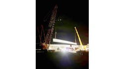
Archer-HNTB has until summer 2013 to open the new bridge, or the team faces a $25,000-a-day penalty. Wasting no time, crews began dismantling the existing bridge in January 2012. The three existing spans were floated out, beginning with the main lift span Feb. 8 under the watchful eye of the Seacoast residents.
Today, the design is 100% complete and the foundations, substructure and approaches are nearly completed. Steel fabrication of the three new truss spans is in progress. Barge assembly of the south truss is currently under way. Each span will be floated in separately with the first span scheduled for January 2013. Float-ins will be timed to take advantage of the Piscataqua River’s high tide—the same method used to place the trusses of the original 1920 bridge. All three spans will be in place by April.
A different framework
The new bridge’s clean form is heavily influenced by current realities of bridge design, where costs are determined less by material use than by fabrication, transportation and erection costs. This framework provides the designer with a fundamentally different set of sensibilities, whereby improvements in structural safety, lower maintenance costs and extended service life can be realized without an increase in overall cost. HNTB’s design for the Memorial Bridge replacement was very much influenced by this philosophical shift in design.
Substructure design
Rather than demolish or reconstruct two of the four main river piers, Archer-HNTB determined the existing piers could be more effective if left in place as an additional element of protection. The granite facing on all four existing river piers was in excellent condition after nearly 90 years in service. As a result, the existing piers were used as cofferdams. Crews drilled through them to install more than a dozen 500-ton-capacity battered micropiles per pier. Independent of the existing piers, the new substructure not only eliminated the need to replace the existing substructure and, thus, all in-water work, but it left the riverbed undisturbed. This solution avoided work-window restrictions imposed by environmental commitments that restricted in-river work only during the cold winter months.
Machinery design
Given the long, successful performance of the existing span drive machinery, a span drive configuration was stipulated in the design-build contract. A typical span drive configuration requires a machine room built above the roadway at mid-span of the lift truss. Instead, Archer-HNTB chose to stow the primary span drive machinery under one end of the bridge and the auxiliary machinery under the opposite side with a cross shaft (situated in the plane of the bottom chord) operating the ropes simultaneously. This configuration offers several advantages:
- Delivers on the primary advantage of a span drive configuration, which is mechanical skew control (ensuring both sides raise and lower at precisely the same speed);
- Allows the entire machinery and drive system to be pre-installed to tight tolerances prior to float in;
- Reduces truss depth and tower height, which simplifies fabrication and erection;
- Protects the machinery from the elements because the machinery enclosures are additionally protected by the deck;
- Eliminates the need for operating rope maintenance and inspection access along the top of the truss; and
- Creates clear, continuous and transparent views of all three spans.
Superstructure design
In the design of the truss, Archer-HNTB hoped to explore new fabrication capabilities to avoid one of the most problematic aspects of truss design: gusset-plate connections. The demise of the existing bridge was in no small way due to corrosion and deterioration of gusseted truss connections, which are difficult to inspect, collect debris, corrode and are impossible to remove and replace without underpinning the structure.
When Archer-HNTB explored this idea during the bid phase, they were convinced the new bridge could:
- Avoid gusset plates;
- Fabricate the top and bottom chords, much in the same way plate girders are fabricated; and
- Use rolled wide flange sections for the diagonals to further simplify fabrication.
This design strategy also offers some unusual advantages. By using plate-girder-type fabrication, there is little or no penalty for increasing the depth of the bottom chord. Because the bottom chord acts as a beam in strong axis bending, it offers the possibility for true truss redundancy, where the loss of a diagonal can be effectively redistributed in chord bending. Rather than using a truss chord depth of 14 in. to 18 in., typical for a 300-ft span, the final design opted for a 36-in. I-section bottom chord.
Second, the truss’s gusset connections are eliminated; diagonals are connected to the chords via a conventional spliced connection. Instead of the connection being at the node, where the diagonals meet the top and bottom chords, the design moved the splice away from the bottom chord and up the diagonals to enhance fabrication, as well as ease maintenance and inspection.
Splicing the diagonals, all of which are I-sections, allowed each flange and the webs to connect independently with independent plates. This configuration precompresses the joint in a highly efficient way. The plates are compact and the bolts are tightly spaced, which helps prevent rust buildup.
The advantages of this system are fourfold:
1. Makes replacement an option. Each flange and web of the truss is connected independently, which allows for piece-wise replacement. This is an enormous advantage over conventional gusset plates, which cannot be partially replaced under load;
2. Minimizes the number of bolts. Because flanges and webs are connected using two sandwich plates, the bolts are subjected to double shear, halving the number of bolts compared with a typical gusset-plate connection;
3. Enhances corrosion resistance. Because the connections are eliminated from locations that attract debris and incorporate flange and web-splice plates that sandwich the primary truss members, the potential for corrosion to compromise bridge service life is much reduced; and
4. Eases inspection. An inspector can walk along the sidewalk and inspect the connections. No special equipment is needed.
Simplified floor-framing system
Another advantage of the deeper bottom chord is that it offers the opportunity to eliminate stringers through the use of intermediate floorbeams that subject the bottom chord to bending, as well as tension. In this arrangement, the deck system spans longitudinally between floorbeams, resulting in a superstructure system that is much easier to fabricate, erect, inspect and maintain.
Truss-span uniformity
All three truss spans have identical geometry, another strategy HNTB adopted to help speed fabrication and erection and, in turn, save costs. This truss design strategy also takes advantage of modern fabrication capability in plate-girder construction, whereby complex geometry easily is cut from a single web plate (or slab).
Because the top and bottom chords are fabricated using plate-girder technology, it is a straightforward process to introduce camber into the geometry with carefully controlled web geometry. The top flange of the top chord and bottom flange of the bottom chord are uninterrupted, as in a conventional plate girder. The top flange of the bottom chord (and the bottom flange of the top chord) is interrupted to allow for the diagonal connections. These interrupted flanges are fabricated into “candy-cane shapes” (i.e., a straight section combined with a curved section to scribe the diagonal connection geometry).
Given that the webs require complex cutouts and the need for discontinuous flanges, it made sense to use the same thickness for each web plate and discontinuous flange, which are both cut from the same plate to minimize waste.
To enhance the flow of forces through the chords, the design strategy requires the use of unusually thick webs and continuous flanges as compared with conventional truss design. This redistributes the flow of forces away from the discontinuous flange in as efficient a manner as possible. The minimum truss-plate thickness is 1 in., thereby providing a robust cross section, which is well able to tolerate local section loss over the service life of the bridge.
Cold-bending
HNTB recommended the use of cold-bending instead of heat-assisted bending to achieve the candy-cane shape based on research conducted by the Texas Transportation Institute and given new guidance in bent-plate fabrication under development by the American Association of State Highway & Transportation Officials. In addition, HNTB decided to use bending radii three times larger than the minimum to enhance ease of fabrication, improve fatigue resistance and minimize steel strength increase due to cold-working and subsequent loss of ductility.
Bending the flanges was an additional cost, but it was compensated by using rolled I sections for the diagonals and fabricating the chords like girders, which increased constructability and reduced fabrication costs because they did not require fabricated boxes, complex connections or sophisticated welds.
Continuous flanges
HNTB designed the bottom flange of the bottom chord and the top flange of the top chord to be continuous. To add the necessary area, designers made the bottom flange of the bottom chord bigger than the top flange of the bottom chord and vice versa. The result is a monosymmetric I section, where the bottom flange is wider than the top flange. This has several advantages:
- The truss acts as a deeper truss;
- It forces some of the load to transfer around the web instead of going back into the web; and
- The bottom chord/bottom flange and the top chord/top flange are wider and heavier.
While there are more than 20,000 truss bridges in service across the U.S., we know of no other bridge that has used this strategy to eliminate gusset plates. It is likely that this modified truss design, using plate-girder fabrication technology, is the first of its kind in North America.
For their sacrifice
Knowing thousands of residents had to sacrifice because of the previous bridge’s closure, we wanted to give them a transportation asset that was cost-effective but also safer, easier to inspect and maintain and less prone to deterioration. We wanted to design and build an asset that, in the end, would make residents feel their hardship was worthwhile. We hope they will be proud of the new bridge, which integrated the innovation of the older bridge and will be marveled by the next generation of bridge designers.
We feel this project accomplishes these goals: that it is not only a new bridge but a bridge that is innovative in design, less expensive to operate and maintain and will outlive the older bridge it replaced. R&B