The scenic north shore region of Virginia Beach, Va., is a popular location for locals and summer vacationers.
The main east-west thoroughfare in this area is Shore Drive (Rte. 60), seeing an average of 40,000 travelers per day. Along Shore Drive are two bridges constructed in 1958 and 1967, respectively. The bridges became a concern to the city and the Virginia Department of Transportation (VDOT) when they were rated as structurally deficient and functionally obsolete. These bridges, named the Lesner Bridges after Senator John Lesner, cross the Lynnhaven Inlet at the base of the Chesapeake Bay. The city and VDOT made a commitment to the Shore Drive community to preserve an effective level of service for the all those who travel along this route. To achieve this commitment, the city required that the design of the project include two new signature bridges with aesthetic lighting, multiuse pedestrian access, open space and landscaping. Additionally, the new bridges were required to be constructed while maintaining four lanes of traffic and a pedestrian path at all times throughout the project duration.
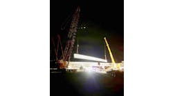
The Lesner Bridges cross the Lynnhaven Inlet at the base of the Chesapeake Bay.
Specialized and innovative
In 2014 construction for the new bridges in Virginia Beach began. The total project cost was $116 million. This included the engineering, design, property acquisition, utility relocation, permitting, landscaping, lighting, inspection and $78 million for construction. The project was funded by the Federal Highway Administration (FHWA), VDOT and the city of Virginia Beach. This Locally Administered Project (LAP) consisted of twin 1,575-ft-long precast concrete segmental bridges. The city’s team of professionals working to accomplish this complex project included designers Clark Nexsen and FIGG Engineering; McLean Contracting Co. and CEI; and consultants RS&H, WR&A and Quinn. The bridge concrete segments were precast in Portsmouth, Va., and delivered to the project using a custom-built 13-axial hauler. These bridges were uniquely designed by utilizing nine typical 150-ft spans with one 225-ft main span. The longer span extending over the navigable channel resulted in the contractor being required to use a combination of both the span-by-span and cantilever erection methods. The prime contractor, McLean Contracting Co., used a custom retrofitted overhead lifting truss to perform the segment erection for this project. The 53-ft-wide segments will accommodate two 12-ft-wide lanes of traffic, with shoulders on each side, as well as a 10-ft-wide multiuse path for pedestrians.
The Lesner Bridge replacement project is making use of specialized design elements and innovative materials, as well as advanced construction processes to deliver a pair of bridges with a 100-year design life. The bridge designer on the project utilized state-of-the-art 3-D modeling as well as a set of detailed segmental construction drawings in the structural design. The bridge plans for the superstructure segments demonstrated fully integrated 3-D graphics and were prepared in multi-color detail with color-coordinated structural elements, utilizing bar-bend detailing as well as post-tensioning hardware consistent with supplier industry standards. The bridge design also displays several forms of aesthetic accent lighting in the pier columns and along the deck exterior edge.
One structural component of the Lesner Bridge project includes the foundation which is supported by multiple 4-ft-diam. drilled shafts approximately 110 ft deep. These shafts are designed for their load capacity to be achieved by skin friction. Bearing capacity can be achieved through skin friction due to the principle of soil freeze. Soil freeze occurs in sandy soils when the soil adheres to the side of the shafts providing resistance to downward pressure. There are 59 drilled shafts in each bridge structure. The drilled shafts in the waterway utilize a permanent steel casing ranging from 30-54 ft in length. The shaft installation process involves drilling using a single flight auger bit as well as a drilling bucket. Polymer slurry is used during the drilling operation in order to maintain an open shaft.
The shaft installation method on land uses a temporary steel casing. Once the shaft is drilled, a pre-tied reinforcing steel cage is set, and concrete is pumped into the shaft using a steel tremie-pipe extended to the bottom of the shaft. The steel reinforcing used in the foundation construction was required to be corrosion resistant reinforcing (CRR). The contractor chose to use MMFX steel for all the structural reinforcing on the project. The MMFX alloy is a low-chromium, low-carbon, high-strength CCR steel. The concrete used for the drilled shafts is self-consolidating concrete (SCC) with a 28-day design strength of 4,000 psi. This type of concrete was chosen due to high pumpability, and it does not need to be consolidated mechanically.
The Chesapeake Bay is an extremely sensitive environmental region. It is the largest estuary in the U.S. and home to many endangered species. For this reason, the drilled shaft operation requires 100% capture. This means that all the drilling spoils and polymer slurry must be captured during the drilling operation. The drilling spoils are collected in a dump barge. On a regular basis the barge is transported by tug, the spoils are excavated and the material is hauled off-site. In addition, when the concrete is being pumped into the shaft the polymer slurry is pumped back into a holding tank on shore. The recharge of the slurry saves the contractor money and protects the environment from any overspills.
Another structural component of the design are the concrete footings and columns. Each bridge is supported by two end abutments and nine footings. Three of the footings were constructed on land and the other six were constructed in the water. The largest footings are adjacent to the channel span, and are designed for vertical load condition, punching shear and horizontal loads to withstand ship impact. During the concrete placement of the footings great care was taken to avoid any accidental concrete being introduced into the waterway. Several concrete capture containers were placed alongside the footing forms during concrete pumping operations. These containers were required to capture any loose concrete that may spill into the bay during the concrete pumping activity. Two different methods of concrete placement for water footings were utilized. The first method was crane and bucket, where the buckets were filled on land and transported by barge, and then lifted at the point of placement by a crane at the footing location.
The second placement method for the footings in shallow water was to place the concrete using a concrete pump with a 140-ft hydraulic boom. Next, the columns were cast in a monolithic concrete placement with no horizontal construction joints. During concrete placement the contractor closely monitored the placement rate to ensure that they did not exceed the fluid pressure capacity of the forms. The columns were designed for the significant construction load, as opposed to a much lower service load for the live load once the bridges are open to traffic. In order to accommodate the large reactions during construction, the top of the columns were designed with five 1.375-in. post-tensioned bars. These horizontal bars are 150-ksi steel, stressed to 120 kips each, and run transversely at the top of the column. This stressing force puts the concrete into compression in the transverse direction and withstands the tension force from loading during construction. The concrete for the columns has a design strength of 4,000 psi and is required to meet a low permeable standard. A striking aesthetic feature of the column will be an arched recess that will house a string of LED lights which will cast light up to the top of the column flare section.
The top of the columns on each bridge are designed with five post-tensioned bars.
Focus on the individual
Finally, the most complex element of the bridges are the individual precast segments. There are a total of 168 segments in each bridge. The casting yard has two casting beds which can be adjusted to create each segment needed for its exact position in the bridge. The concrete used for the segments ranges from 6,000 psi to 8,000 psi and is required to be low permeability, less than 1,000 coulombs. The reinforcing steel also is MMFX steel. The segments were cast using the short line match-cast process. The match-cast process involves each segment being cast next to the previous segment in the span to ensure a perfect fit. When the casting of each span was complete, the geometry control program generated a “casting curve.” This curve established the horizontal and vertical values that the segments were erected to at the bridge site.