South Korea’s largest infrastructure project is expected to open in December 2010, and the crossing will significantly reduce what is currently a three-hour commute time between the city of Busan and Geoje Island, home to two of the world’s biggest shipyards.
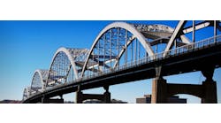
Being built by GK Corp., a consortium of seven Korean contractors led by Daewoo Engineering and Construction, the $2.5 billion Busan Geoje Fixed Link is an 8.2-km, four-lane highway made up of two cable-stayed bridges and the world’s deepest immersed roadway tunnel. The route crosses three navigation channels that provide access to Busan’s new port and to naval dockyards. The project is divided into three sections:
Lot 1 Cable-Stayed Bridge: A 1.65-km, three-pylon cable-stayed bridge with approach viaducts between Jeo and Geoje islands;
Lot 2 Cable-Stayed Bridge: A 1.87-km, two-pylon cable-stayed bridge with approach viaducts between Jungjuk and Jeo islands; and
Lot 3 Immersed Tunnel: A 3.2-km immersed tunnel between Gaduk and Daejuk islands.
With erection of the final key segment of the cable-stayed bridges and completion of the immersed tunnel closure joint in early June, the project is over 90% complete.
The remote site has water depths up to 30 m for bridge foundations and is totally exposed to severe open sea conditions from the Pacific Ocean. This led to a design and construction philosophy of extensive prefabrication and sea transportation of the large prefabricated elements.
Two high, one deep
The project will carry the national road NR 58 across three navigation channels that provide access to the new Busan port and to naval dockyards, linking Gaduk Island near the city of Busan to Geoje Island via Daejuk, Jungjuk and Jeo islands. These are linked by the three principal elements of the crossing.
Daejuk and Jungjuk islands are connected by a short causeway, and with bored tunnels on both Jungjuk and Jeo islands, crews are able to bypass the rugged terrain. The presence of the naval dockyard placed a requirement on the concessionaire to provide, for security reasons, a tunnel under the principal navigation channel rather than a bridge. At a depth of 48 m, the 3.2-km-long immersed tunnel will be the deepest concrete immersed highway tunnel in the world. This was just one of the major challenges facing the project team on both the bridges and the tunnel, and a holistic approach, including precasting of a significant part of the project, was adopted. The major elements of the tunnel required the establishment of a substantial precasting yard, which made it economical to consider precasting the remaining marine elements of the link including the bridge foundations. Precast caisson foundations were thus the natural choice.
Daewoo directive
The concession for the design, construction, financing and operation of the link was awarded to a consortium led by Daewoo E&C Ltd. in 2002, following protracted but ultimately unsuccessful discussions with international partners, during which time the concept designs for the crossing were developed. Design and related contracts were awarded in 2003, with site activities starting in earnest in 2004 for the projected six-year construction program.
The project organization is typical of other recent public-private partnership projects in Korea. As lead company, Daewoo is supported in a joint venture by six other Korean companies, with subcontracts for specialist suppliers. Daewoo also engaged in a joint venture between Halcrow Group Ltd. of the U.K. and Tunnel Engineering Consultants (TEC) of the Netherlands to provide technical advice on both the design and construction of the link, including the preparation of the contracts for the designers, checkers and supervisors. After a competitive tendering process in 2003, Daewoo appointed a consortium led by Cowi A/S of Denmark with Dasan and DM Consultants of Korea to carry out the detailed design of the bridges. Other appointments included Yooshin, in association with Ingerop of France, to carry out the design checking and design supervision roles, and with Mott MacDonald to provide the construction supervision services.
Lots of construction
The 29 superstructure spans for the approach bridges are up to 90 m long, weigh up to 2,427 tonnes and consist of 3- x 3.6-m-deep longitudinal steel-plate girders with bolted cross girders at 9-m centers, composite with a 300-mm-thick concrete deck slab. After prefabrication at Obi Bay, the spans were skidded to the waterside for transport to the site by a floating crane. The three-pylon cable-stayed bridge, forming part of Lot 1, has a total length of 676 m, side spans of 108 m and twin main spans of 230 m. The bridge provides a navigation clearance of 202 m x 36 m in each channel. The geology of the site generally comprises marine deposits (sandy and clayey layers) overlying residual soil (formed by decomposing and weathering of the bedrock in places) and bedrock. The nature of the bedrock is variable and consists of Cretaceous mudstones, tuff, sandstones and granite. These can be broadly classified into two groups as “weak rock” and “hard rock.” The foundations for the Lot 1 bridge piers are cellular caissons founded on weak or hard rock, located in up to approximately 30 m of water. Viaduct and anchor pier shafts are precast concrete, and the three 103-m-high pylons are cast in situ with the legs providing a signature gentle curve in transverse elevation. The lower pylon legs taper inward toward the caisson foundations, reducing the plan area of the foundations.
The superstructure consists of 2-m-deep outer steel-plate girders, welded cross girders at 4-m centers and a 260-mm-thick concrete deck with longitudinal post-tensioning at thickened ends and at midspan. The concrete deck slab is formed from prefabricated panels, joined by concrete in situ connections, and carries the highway comprising two 3.5-m-wide lanes and a 2-m-wide emergency lane in each direction. Torsional stiffness of the structure is provided by the cables anchored along each edge of the deck, thus allowing the economical composite plate girder form of construction to be chosen. Tie-down cables are provided at the anchor piers to resist uplift forces from the side-span cables.
The two-pylon cable-stayed bridge has a main span of 475 m and side spans of 222 m with 158-m-high pylons. It provides a single navigation channel clearance of 435 m x 52 m.
The foundations are generally similar to those of the bridge in Lot 1, except for the presence of an ancient valley in the bedrock in-filled with approximately 18 m of marine clay requiring the anchor pier and the adjacent approach viaduct pier on the Daejuk Island side of the bridge to be supported by 16 and 12 piles, respectively, each being 2 m in diameter by 60 m in length.
The superstructure is similar to the three-pylon bridge, with the exception that an additional crawler lane is provided on one carriageway to accommodate the steeper gradient as the highway leaves the tunnel and climbs to achieve the required clearance over the navigation channel.
Articulation of both bridges is unusual in that the superstructures “float” past the pylon locations unsupported vertically. For each bridge, bracket bearings at one pylon give longitudinal fixity, with lateral wind and seismic forces being taken on bearings and shock transmission units located between the pylon legs and the deck. Vertical and transverse forces are taken by pot bearings at the side-span anchor piers.
Each of the five superstructure starter segments (pier tables) was prefabricated complete with its concrete deck slab, lifted onto temporary supports on the pylon lower cross beam by floating crane and held by two temporary cables suspended from an upper cross beam until permanent cables were installed. The two-pylon bridge used 24-m-long, 630-tonne pier tables that were placed in one operation onto their temporary supports. The three-pylon bridge used 46-m-long, 990-tonne pier tables that were initially placed 5 m through the pylon legs and temporarily supported at one end to allow repositioning of the lifting points and then partially lifted and skidded another 6 m into final position.
After securing each pier table, a derrick crane was erected allowing the lifting of the first steel segment, cable works and precast deck slab erection. Space was then available for erection of a second derrick crane and the start of the balanced cantilever construction.
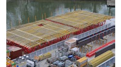
The main lengths of the cable-stayed superstructures used 110 prefabricated steel segments 12 m long and up to 96 tonnes, which were barged 30 km to the site after trial assembly at the fabricator’s Changwon works. They were lifted by derrick crane, bolted to the previous segment and attached to two stay cables, which were given first stage stress. Six precast deck panels barged 35 km from Obi Bay were then placed by derrick crane and connected to the steelwork with in-situ stitches. Concrete for the in-situ stitches was supplied from a floating batching plant and skipped by mobile crane to deck level, where it was transported by wheelbarrow to location. To ensure 30 MPa before the second stage cable stressing and 40 MPa in the stitch concrete before lifting the next segment, steam heating was used during winter months when ambient temperatures dropped as low as -14°C.
Each end segment was prefabricated at Obi Bay complete with its thickened concrete deck and lifted by floating crane onto temporary steel supports on the anchor piers. For each side-span key segment, after survey of the gap to the end segment, the steel was cut to length and finalized. With the gap temporarily increased by 150 mm using longitudinal jacking, the key segment was erected and aligned vertically using ballast. The gap was then closed, bolt holes surveyed and splice plates for connection to the end segment accurately fabricated. During the making of the splice plates, an open 100-mm gap was maintained between the side-span key and end segments. After finalizing end segment position, the pot bearings were grouted, loaded with the end segment and then connected to the edge girder lower flanges. The tie down was then stressed to 30% to secure the end segment to the anchor pier during alignment and connection of the side-span key segment. On delivery of the splice plates, the 100-mm gap was closed and the bolted connections completed. At this stage the structure was vulnerable to wind-induced loading so temporary horizontal bracing was provided.
Being located in the open sea, the bridges are exposed to extreme wind and wave conditions from typhoons during June to October when one to three storms can be expected annually. During basic design in September 2003, typhoon Maemi, Korea’s worst recorded typhoon, hit Busan, causing extensive structural damage, claiming 117 lives and stripping vegetation from the rock-cliff faces of islands close to the bridge sites. Based on this experience, the bridges are designed for wave heights of up to 13 m with critical wind speeds up to 80 m/s, and wind affects on the partially built structures were closely analyzed.
For erection of the three-pylon bridge, stabilization during strong winds was provided by a temporary tuned-mass damper (TMD) system developed in conjunction with the Daewoo Institute of Construction Technology. Only the two pylons that had the possibility of having wind-sensitive superstructure stages during the 2009 typhoon season had the TMD installed.
For the erection of the two-pylon bridge, stabilization by TMD was impractical, because of the larger physical size required, so it was designed to have temporary tie-downs positioned on the superstructure cantilevers at the fifth and 10th cable anchorages on each side of the pylons. Each 5-MN-capacity tie-down consisted of 2- x 16-strand cable bundles with dead-end anchorages cast into a 2-m-diam. seabed anchor pile and temporary deck-level anchorages above the edge girders for live end stressing.
With an external width of 26.5 m and a length of 3.24 km, the tunnel incorporates two lanes of traffic in each direction and a central services/escape tunnel. The tunnel is divided into 18 precast submersion elements each 180 m in length. These are cast in the drydock at the Anjeong precasting yard located on the mainland to the east of Geoje Island. Up to five 180-m-long tunnel elements are cast at a time.
The joints between the segments have two water stops: an injectable water stop and an omega joint. At either end of each element is a temporary steel bulkhead that seals the tunnel section when it is floated out from the casting yard to the previously prepared trench at the tunnel location. The 12.5-m-deep trench for the immersed tube was dredged through soft clay giving way to bedrock toward each end. Most of the tunnel sits on the very soft mud and clay, and cement deep mixing soil improvement was carried out. In this process, cement and soil are mixed to form soil-cement columns over the area of weak ground. The tunnel elements are placed on a gravel bedding layer in the trench.
The past five months, when 10 cantilevers have been under simultaneous construction, has taken the bridges to structural completion with three months remaining before the crossing is expected to open in December 2010.


