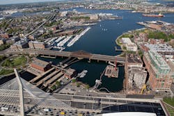
Boston’s 120-year-old North Washington Street Bridge over the Boston Inner Harbor carries 42,000 vehicles per day, heavy pedestrian traffic and numerous utilities from Boston’s North End and West End areas to Charlestown.
Among the vehicles crossing the bridge each day are four major bus routes of the Massachusetts Bay Transit Authority (MBTA), school buses, intercity buses, tour buses and area shuttles, as well as hazardous cargo vehicles. The heavy vehicular and pedestrian traffic are no surprise, as the bridge is the easterly most bridge carrying a local roadway and pedestrians across the Boston Inner Harbor at the mouth of the Charles River.
The bridge is located one block from the MBTA’s North Station which is a major transportation hub for Amtrak, MBTA Commuter Rail, MBTA’s Orange and Green subway lines and several bus routes. Directly above North Station is the TD Boston Garden, which is home to the Boston Celtics and Bruins, as well as the host of many other sporting and entertainment events. In addition to the commuters and event goers, the east sidewalk carries Boston’s Freedom Trail to the Bunker Hill Monument and U.S.S. Constitution located in the Charlestown section of Boston.
The existing North Washington Street Bridge is located adjacent to the iconic Zakim Memorial Bridge.
Starting with what’s wrong
The existing bridge is classified as functionally obsolete and has been classified as structurally deficient since 2003. At that time the center two lanes of the 240-ft-long truss span were permanently closed to traffic due to deterioration. Since that time, ongoing inspections and repairs have been performed in order to keep the remaining four travel lanes and sidewalks open to traffic.
The existing roadway and sidewalk decking of the main 240-ft-long truss span consists of open-grid metal decking which has openings to the water below. These open surfaces are less skid-resistant than solid decks, create high noise levels and vibration from vehicle traffic, and cause discomfort for the many cyclists and pedestrians crossing the bridge. Additional noise and vibration are experienced as each vehicle impacts the dozen expansion joints along the structure. Each cyclist crossing the bridge needs to choose between braving the open-grid roadway surface carrying two lanes in a 22 ft width between the trusses, or dismounting and walking the 1,087-ft crossing on the crowded sidewalks.
In 1961, the operable swing span of the existing bridge was allowed to be permanently fixed in the open-to-vehicles position and limit the height of the navigation channel under the bridge. Since that time, electrical transmission lines, electrical power distribution lines, communications lines, gas and water mains, and traffic signal interconnection lines were added to the fixed structure. These utilities now create additional challenges in replacing the bridge, as they need to either be relocated or supported in place during the bridge reconstruction.
A unique place in itself
As the North Washington Street Bridge is eligible for listing in the National Register of Historic Places, in conformance with the National Historic Preservation Act, a Memorandum of Agreement was issued and signed by the Federal Highway Administration (FHWA), the State Historic Preservation Officer (SHPO), the MassDOT Highway Division and the city of Boston. This agreement stipulated that the proposed replacement structure would be a Gateway bridge with architectural design elements that would incorporate the new bridge structure into its surroundings, distinguishing the crossing as a unique place in itself and include architectural design of structures, lighting, overlooks, separated bicycle lanes, and other elements to encourage use by people of all ages and interests.
Once the parameters were set, the design team, consisting of the Boston Public Works Department, the Massachusetts Highway Department, Alfred Benesch and Co., and Rosales + Partners began the design process. The highly collaborative process solicited stakeholder feedback as required, in order to find solutions while working within all of the constraints.
A 7-ft-wide bicycle lane and a 10-ft 6-in.-wide sidewalk will be provided along each side of the bridge to accommodate bicycle and pedestrian traffic.
Accepting all kinds
Finding a transportation structure that encourages the multiple modes of transportation for both the commuter and the recreational traveler was the result of cooperation with many public agencies, advocacy groups and public meetings. It was agreed that the roadway would be 57 ft 6 in. wide, and consist of two travel lanes in each direction and one bus rapid transit (BRT) lane in the southbound direction. The BRT lane will help to alleviate the congestion for the high-occupancy buses and shuttles that cross the structure each day.
A 7-ft-wide bicycle lane would be provided along each side of the bridge to allow cyclists to travel in the direction of vehicle traffic. The bicycle lanes would have to extend to and be incorporated into the adjacent signalized traffic intersections on either side of the bridge. The bicycle lanes would be separated from the hazards and noise of the vehicular traffic with a 3-ft 9-in.-wide traffic barrier/planter complete with an irrigation system. These longitudinal planters also provide the space required to support roadway and pedestrian lighting. The separated bicycle lanes provide a clear path for commuter cyclists, and also provide the protection and comfort to encourage the recreational family or novice cyclist to make the crossing.
A 10-ft 6-in.-wide sidewalk will be provided along each side of the bridge to comfortably accommodate the pedestrian traffic. Both sidewalks will be protected and decorated with an illuminated stainless-steel pedestrian railing. The sidewalks will widen up to a 19-ft-wide overlook over a 240 ft length at the center of the bridge crossing and the navigation channel. These overlooks will contain architectural benches, tree planters and landmark plaques that describe each of the landmarks that are visible from the bridge. A 285-ft-long by 33-ft-high architectural trellis will be constructed in each of the barrier/planters that will mark the center of the navigation channel crossing, and will extend up to 26 ft over the bicycle lane and widened sidewalk to provide partial shade. The architectural trellis will be illuminated with accent lighting visible from the water and banks of the harbor, and will mark Gateway at the Charles River Estuary. The approach sidewalks will contain an interpretive panel with images and a description of the history of the crossing. The overlooks, benches, trees, information panels, and the architectural trellis will create a unique destination that is separated from vehicular traffic via the longitudinal planters and that is accessible for use by people of all ages and interests as well as those traveling from afar to travel along Boston’s Freedom Trail.
The roadway along the bridge will be 57 ft 6 in. wide, consisting of two travel lanes in each direction and one BRT lane in the southbound direction.
Standing with Leonard
The North Washington Street Bridge is located adjacent to the iconic Leonard P. Zakim Bunker Hill Memorial Bridge (Zakim Bridge). The Zakim Bridge is the widest cable-stayed bridge in the world and is recognized by its 330-ft-tall inverted Y-pylons that are displayed with the skyline of Boston in nearly every televised newscast and sporting event held at the TD Boston Garden. The Zakim Bridge is visible from many vantage points in the city and can be seen close up while driving on I-93 or while on the river walks that connect the parks along the Charles River. The proposed structure would need to complement and not compete with the highly visible Zakim Bridge.
After studying many alternatives, the selected alternative consisted of a platform bridge that functioned as a viewing platform for the Zakim Bridge. The proposed structure was not to rise above the roadway, as that could compete or conflict with the towers of the Zakim Bridge. The architectural trellis described above would instead mark the crossing for motorists, cyclists, pedestrians and boaters. The focal point of the structure had to come from the structure below the roadway. Due to the corrosive marine environment, the superstructure needed to remain as high above the water as possible. This led to the concept of having a very simple superstructure with a uniform depth and allowing the substructure to create the unique identity of the proposed bridge.
One desire was to create an open substructure that would increase visibility and reflective light rather than the dark shadows and obstructed views created by the existing massive stone wall piers. The proposed structure would need to be constructed in stages in order to maintain vehicular traffic and utility operations during bridge reconstruction. The proposed structure also would need to be constructible in the 12-ft tidal fluctuations of the harbor and not exceed the limited funding available from FHWA, MassDOT and the city of Boston. The substructure also would have to be positioned at locations that do not interfere with the existing bridge foundations and that allow for navigation during bridge reconstruction. After many studies, investigations and design iterations, it was decided that the proposed bridge would be constructed with five reinforced concrete V-piers. These V-piers would provide a unique notable structure that complements and reflects the iconic inverted Y-pylons of the Zakim Bridge. These piers will be illuminated with accent lighting with colors that can change to match those of the Zakim Bridge with each holiday or special event.
The design of the new North Washington Street Bridge structure needed to complement and not compete with the highly visible Zakim Bridge.
The need for a temp
Closing the bridge to vehicular and pedestrian traffic was not an option due to the amount of traffic and lack of feasible detours. The original 240-ft truss span consists of four trusses that create three two-lane roadways. As mentioned previously, the center two lanes have been closed for 15 years due to deterioration. Replacing the bridge in three main stages would only provide long and narrow construction zones, and would restrict the size of construction equipment that could be used. Traffic counts indicated that during construction, two lanes would need to be provided in the southbound direction and one lane would need to be provided in the northbound direction. For these reasons, a temporary vehicular bridge carrying three lanes of traffic and one sidewalk would be needed and would be able to allow the bridge to be constructed in two main stages.
The numerous utilities crossing the bridge also needed to maintain operation throughout the bridge reconstruction. One of the most restrictive utilities on the bridge are two 115-KV high-pressure fluid-filled transmission lines located below the west sidewalk. These transmission lines cannot be moved and need to be supported in place 10 ft on center throughout each stage of construction. Many of the other utilities are located in various spots and would need to be temporarily relocated several times due to the bridge reconstruction phasing. For these reasons, it was decided that the first stage of the project would be to construct a full-length temporary utility bridge along the existing west sidewalk. This utility bridge would be used to support the transmission lines in place and all of the other utilities could be relocated onto this temporary utility bridge to clear the way to reconstruct the main portions of the bridge.
The proposed bridge would now have to be able to be constructed while this temporary utility bridge was in place. The superstructure would have to be able to be constructed in place and be able to support cantilevers that could be added later to support the sidewalks and the overlooks on the main span. Since it also was desirable to construct the superstructure in two main stages and be naturally aesthetically pleasing, it was decided that the superstructure would consist of four torsionally rigid trapezoidal steel box girders. Each trapezoidal steel box will have 8-ft-wide bottom flanges, and the top flanges will be spaced 11 ft on center to allow for a conventional reinforced concrete composite deck to be used. Steel floorbeams will be added to cantilever out 13 ft from the box girders to support two stringers, the sidewalk, transmission lines and other utilities. The length of the cantilevered floorbeams increase up to 21 ft in the main span to support the overlooks. All of the steel elements will be metalized and painted for protection from the marine environment. Fiber-reinforced polymer panels will be used as an architectural screen along the bridge fasciae to conceal the numerous utilities.
The trapezoidal box girders will consist of 11 continuous spans over the 1,087 ft length. The location of the five V-piers was selected in order to avoid the existing piers and to allow continual navigational traffic to the three locks entering the Charles River Basin. There is a 50-ft span located above each of the V-piers and the spans between the V-piers and the abutments range from 103 ft to 190 ft. These span arrangements allow for trapezoidal box girders with a constant 6 ft 6 in. depth for economy and ease of future bridge inspections.
Each pier support location will consist of four individual V-pier columns, arms and tie-beams. One V-pier column will be located below each of the four trapezoidal box girders of the superstructure. This will provide the open concept designed to allow more visibility and reflective light. Each arm of the V-pier extends out 25 ft from the column and rises up 20-30 ft above the water. The stems and arms of the V-piers will be constructed with high-performance concrete with conventional epoxy steel reinforcement. The top of the arms will be tied together with a post-tensioned concrete tie-beam. The vertical portions of the V-piers will be exposed during low tide and hidden during high tide.
The four columns of each individual V-pier share a common concrete pile cap footing. In order to minimize the cost of the cofferdams, dewatering and excavation into the riverbed while minimizing the visibility of the footings, the top of the pile cap footings were set below the mean low water elevation. These set the bottom of the pile cap footings anywhere from 6 ft below the mudline to 12 ft above the mudline.
Each of the pile caps will be supported by eight 6-ft-diam. reinforced concrete drilled shafts that extend down 30-80 ft through layers of silt, sand and till and continued another 10-27 ft into bedrock. The top 6-10 ft of the drilled shafts will be encased within a concrete tremie that will aid in the dewatering of the areas in order to constrict the pile caps and columns of the V-piers.
The proposed North Washington Street Bridge was designed to meet the functional needs of the structure while providing the Gateway structure that could be incorporated within the context of its surroundings.
Opposites are attractive
The proposed North Washington Street Bridge was designed to meet the functional needs of the structure while providing the desired Gateway structure that could be incorporated within the context of its surroundings. The Zakim Bridge provides the dominant massive structure that carries the interstate traffic in and out of Boston, while the North Washington Street Bridge provides a less intimidating structure that can be driven over, walked over, sailed under, rested on and enjoyed by people of all ages and interests. The bridge reconstruction contract was awarded to J.F. White, and they received Notice to Proceed in August 2018 with an estimated completion date of November 2023.


