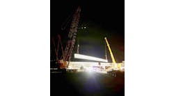
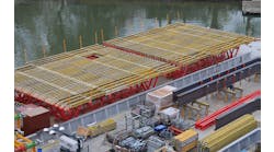
In August 2008, a fiber-reinforced polymer (FRP) bridge superstructure was installed in Huron County, Ohio, with funding provided by a Federal Highway Administration Innovative Bridge Program Grant.
This successful installation of a single-span (approximately 17 ft) FRP bridge was the result of months of testing and fabrication and was followed by several truck tests that verified the bridge’s structural integrity. The selected FRP superstructure was a fiber-reinforced polymer honeycomb (FRPH) sandwich panel bridge deck, which replaced a treated wood deck with an asphalt overlay on steel beams built in 1976.
As each FRPH product is unique, overall strength and stiffness tests are necessary to verify each FRPH bridge’s integrity. There are several uncertainties that testing can eliminate:
- Each bridge is individually produced in a manual process called “wet lay-up” which introduces material and geometry property uncertainties into fabrication;
- A uniform code or accepted procedure for the design and fabrication of FRPH bridges does not exist; and
- The load distribution between FRPH bridge panels is difficult to determine.
-
The following is a description of the design and fabrication, the results of the laboratory testing of a full-scale prototype FRPH bridge panel and the results of low-speed (crawl) truck tests conducted on the FRPH bridge deck during October 2008 and 2010. Serious stiffness The existing reinforced concrete abutments of the bridge were in good condition and were reused. Since they were not founded on piles, it was necessary that the replacement superstructure not increase foundation loads. A typical concrete and steel superstructure weighs more than double that of the existing superstructure, making FRPH rehabilitation attractive. Additionally, FRPH bridges offer significant advantages in their resistance to salts, moisture and decay and can produce a bridge with an expected life span of up to 100 years. Huron County selected W.E. Quicksall and Associates Inc. (WEQ) for the design of the Innovative Bridge Project. The structure is governed by stiffness rather than strength, so deflection criterion was used to design the FRPH panels. The design deflection ratio was L/1000, which exceeds the requirement of L/800 (AASHTO 2007), and was chosen because of the uncertainties in the material over time. Kansas Structural Composites Inc. (KSCI) was awarded the contract to manufacture the FRPH panels. During construction, the existing concrete abutments were retrofitted for the placement of four 16 ft 9¾-in.-long by 6 ft 5¼-in.-wide by 21-in.-deep FRPH panels, which span between the abutments. The alternate military load, consisting of two axles spaced 4 ft apart with a load of 24 kips per axle (AASHTO 2007), was the controlling load for the design. This load produced a bending stress of 1,020 psi in the top structural surface, which was well below the allowable stress calculated from the prototype test. Made with an E A visit to Kansas allowed for a better understanding of the fabrication process, quality control, observation of bridge panel construction, close-up inspection of the No-Name Creek Bridge (the nation’s first all FRPH bridge) and meetings with Dave Meggers of KDOT, Jerry Plunkett of KSCI, Dr. Youchi Wang of Kansas State University (KSU) and their respective staffs. FRPH bridges, such as the No-Name Creek Bridge and the Huron County Bridge, are single-span honeycomb core beam bridges. The core is composed of alternating flat vertical sheets and corrugated vertical sheets. The flanges are flat elements attached to both faces of the core, perpendicular to both the flats and flutes. The depth of the core and thickness of the flange are determined based upon the required design strength and desired span-to-deflection ratio of the bridge. The honeycomb core was assembled from flat sheets and corrugated flutes; then a layer of chopped strand mat was applied over (normal to) the core. On top of the chopped strand mat, layers of directional strand mat were built up until the desired flange thickness was reached. Resin was hand applied to each mat as it was placed. The fiber sheets used in fabrication are composed of E-glass fibers, which are bound in a matrix of epoxy. The material is hand-assembled in a process called wet lay-up. Because wet lay-up is a manual process, the modulus of elasticity and moment of inertia can vary considerably from panel to panel based upon the amount of epoxy and E-glass. This contributes to the difficulty in making precise design calculations or finite-element modeling. FRPH cross sections can be related to I-beam cross sections, as the core transfers the shear and provides distance between the top and bottom flanges, while the flanges accommodate the bending moment through axial tensile and compressive forces. While FRPH sandwich panel testing has been done by several institutions, including KSU, the mode of failure has always been the same. At the ultimate load, separation occurs between the core and flange, and the panel elements collapse. Failure is a result of the relatively weak joint between the core and flange interface. Testing of the prototype at the University of Cincinnati generated data that was used to evaluate the strains and deflections measured in the truck test to ensure that the strains and deflections were consistent and within the design limits of the bridge. The prototype was 16 ft long, 32 in. wide and had a depth of 21 in. The test consisted of four-point bending, and the specimen was simply supported by steel rollers. The test load sequence was a series of monotonically increasing load-unload cycles. This permitted observation of hysteresis. Strains measured during the prototype test confirmed the design assumption that plane sections remained plane and indicated that the shear strength of the core flange joint is adequate. The FRPH had a linear elastic stress-strain relationship up to failure. The average of the midspan strain gauges at ultimate strain was approximately 6,400 microstrain. The prototype panel failed at 135 kips per actuator, nine times the anticipated service load of 15 kips per actuator. The failure mode was sudden delamination of the top face from the core at the core-to-flange joint, which was expected. The midspan deflections measured exceeded L/1,000 for the alternate military loading, which was KSCI’s design deflection limit. KSCI addressed this excessive deflection by adding extra E-glass and epoxy layers to the top and bottom flanges of each bridge panel, increasing the flange thickness from ½ in. to 7?8 in. Carrying trucks Truck tests were performed in 2008 and 2010. The main objectives of the truck tests were to verify the strength and stiffness of the bridge. Two double-axle trucks loaded with gravel were used for both the 2008 and the 2010 truck tests. The test procedure was the same for the 2008 and 2010 tests. Instrumentation for the truck test included strain gauges and LVDTs. Eight strain gauges (two per panel, one each at midspan top and bottom locations) and four LVDTs (one per panel at midspan) were utilized. The trucks were positioned in a staggered formation to account for the 25° bridge skew, so that the back truck axles crossed midspan at the same time. Data was collected as the trucks slowly rolled across the bridge. Single and double truck passes over the bridge were conducted from the north and south directions. This test is easy to replicate, which allowed 2010 truck test data to be compared with the data collected in 2008. Strain gauges were left on the bridge after the 2008 test, which kept gauge location consistent for 2010. LVDT locations also were identical for both tests. In 2008 and 2010, the same test procedure was followed. Truck weight and speed varied, so it was necessary to scale the 2010 data. The bridge span is oriented north-south. For this test, both trucks were driven south across the bridge. The resulting strains provide a clear picture of the behavior, because the movement of the truck during data recording allows a comparison of the unloaded bridge, bridge loaded with the front axle, bridge loaded with the heavier rear axles and finally unloaded again. The truck test saw maximum deflections of about 0.04 in., which is well below the chosen L/1000 deflection limit of 0.2 in. The maximum strain recorded during the truck test was about 125 microstrain, far below the ultimate strain of 6,400 microstrain recorded during the prototype test failure. After time and magnitude scaling, the variation of deflections from 2008 tests to 2010 tests varied from 8.8% to -12.4% for three of the LVDTs. The fourth LVDT had an increase of 40% compared with the 2008 test. In the 2008 test, the peak appeared to be clipped. In all cases, the deflection remained well below the deflection limit of 0.2 in. The overall fit of the two tests is good. Safe to use The FRPH bridge provided a satisfactory lightweight solution for replacement of a steel stringer and wooden deck bridge. Prototype testing provided service and ultimate strains and deflections, which were compared with bridge truck testing. Objectives of the bridge truck testing were to ensure that strains recorded during the truck test were far below the ultimate strain, verifying that the bridge was safe for vehicle traffic. This was accomplished by comparing prototype strain values with the truck test strain values. Truck testing also provided consistent deflections that were below the L/1000 deflection limit. Comparisons between data recorded in 2008 and 2010 showed little difference in deflection and strain. This validated the first test data and showed the bridge stiffness is not degrading. Erection of the Huron County FRPH bridge took about one work day. This bridge, and others like it, demonstrates the real potential and construction feasibility for this material to be used in single-span bridges. However, unresolved issues such as quality and consistency of workmanship, the lack of design codes and standards and high cost prevent this type of bridge deck from widespread application.


